
Electric connection of electrochemical and photoelectrochemical cells

a photoelectrochemical and electrochemical technology, applied in the direction of cell components, final product manufacturing, sustainable manufacturing/processing, etc., can solve the problems of reduced light transparency, reduced electrical conductivity, and large space occupation of process equipmen

Inactive Publication Date: 2003-12-02
FORSKARPATENT I UPPSALA
View PDF12 Cites 90 Cited by
  • Summary
  • Abstract
  • Description
  • Claims
  • Application Information

AI Technical Summary

Benefits of technology

The method of the invention provides advantages, as compared to previously known methods described above, such as no or reduced need for high temperature or vacuum environment, no need for masking and comparatively inexpensive process equipment. Furthermore, according to the invention a chemical protection of the wire, as well as a separating barrier between adjacent cells in a multi-cell assembly, is provided at the same time as the electrical connection is established.

Problems solved by technology

Thus, in order to achieve a high conductivity a comparatively thick conducting layer has to be applied resulting in reduced light transparency.
On the other hand, to achieve a good transparency a thin conducting layer should be applied resulting in reduced electrical conductivity.
1) Deposition by evaporation. Using this method, the electrical connecting means are formed by depositing strings of highly conductive materials from vapor of, for example, metals or highly doped metal oxides. As the melting temperature of the evaporated material often is high, the depositing process has to be carried out at high temperature and vacuum conditions. The process equipment requires a lot of space. The method requires that a mask is placed in front of the substrate.
The process equipment requires a lot of space and high investment costs.

Method used


Image

  • Electric connection of electrochemical and photoelectrochemical cells
  • Electric connection of electrochemical and photoelectrochemical cells
  • Electric connection of electrochemical and photoelectrochemical cells

Examples


first embodiment

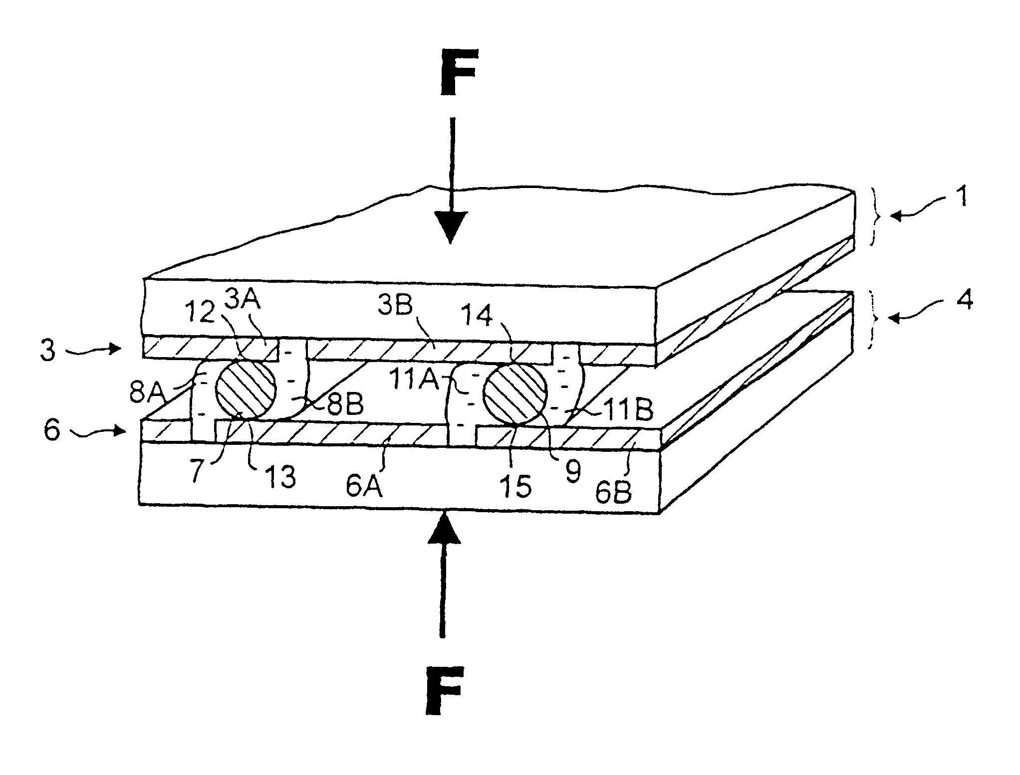
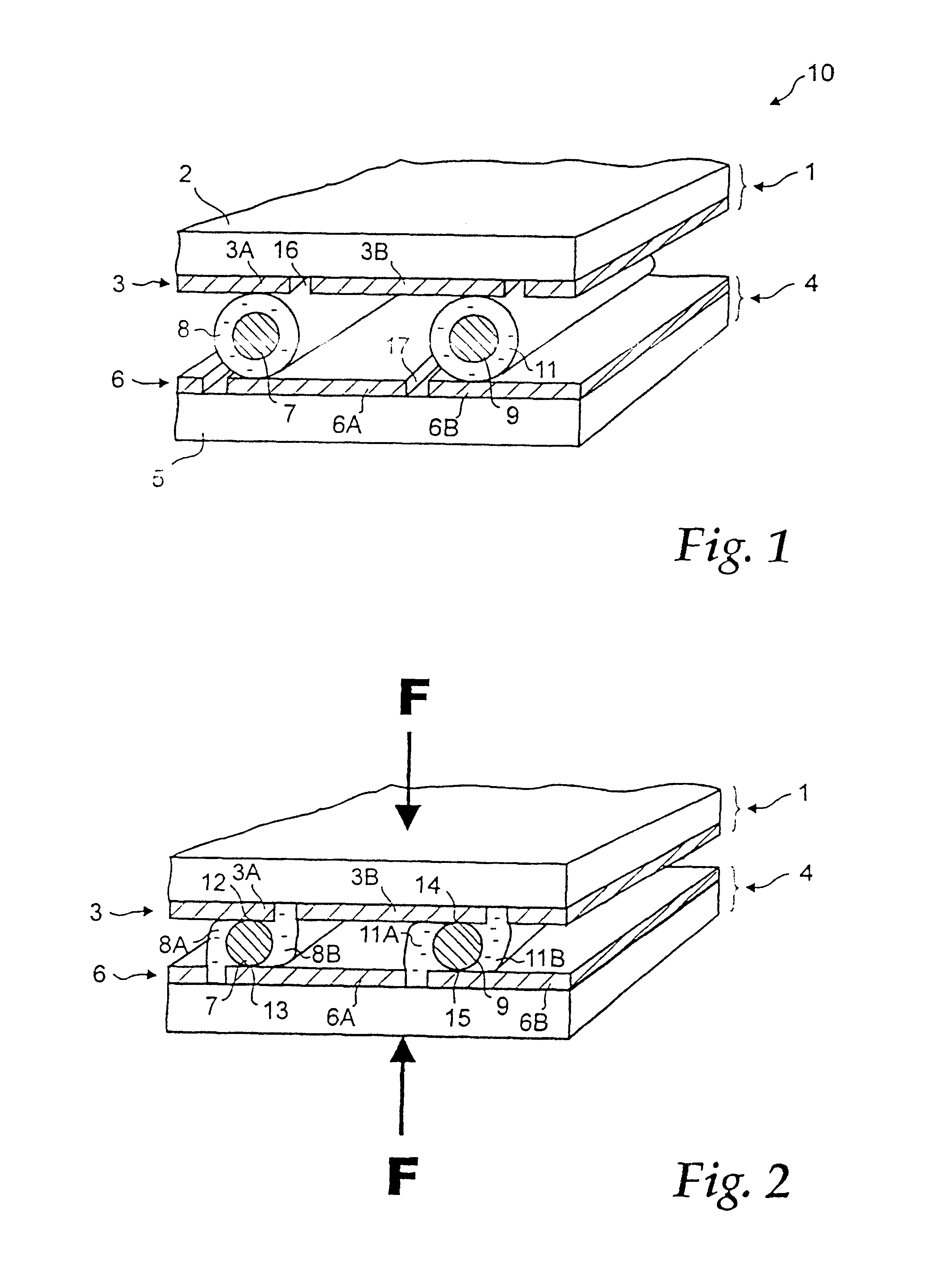
A first detailed, not limiting example of the present invention shall now be described, with reference to FIGS. 1-5, wherein each conducting glass 1, 4 consists of a 10.times.10 cm square transparent soda lime glass substrate 2, 5 of 3 mm thickness.

Each conducting glass 1, 4 has on one side a conductive surface layer 3, 6 of fluorine doped tin oxide. The resistivity of the conducting layer is 8 Ohm / cm.sup.2, and the transparency is 80% in the visible light range.

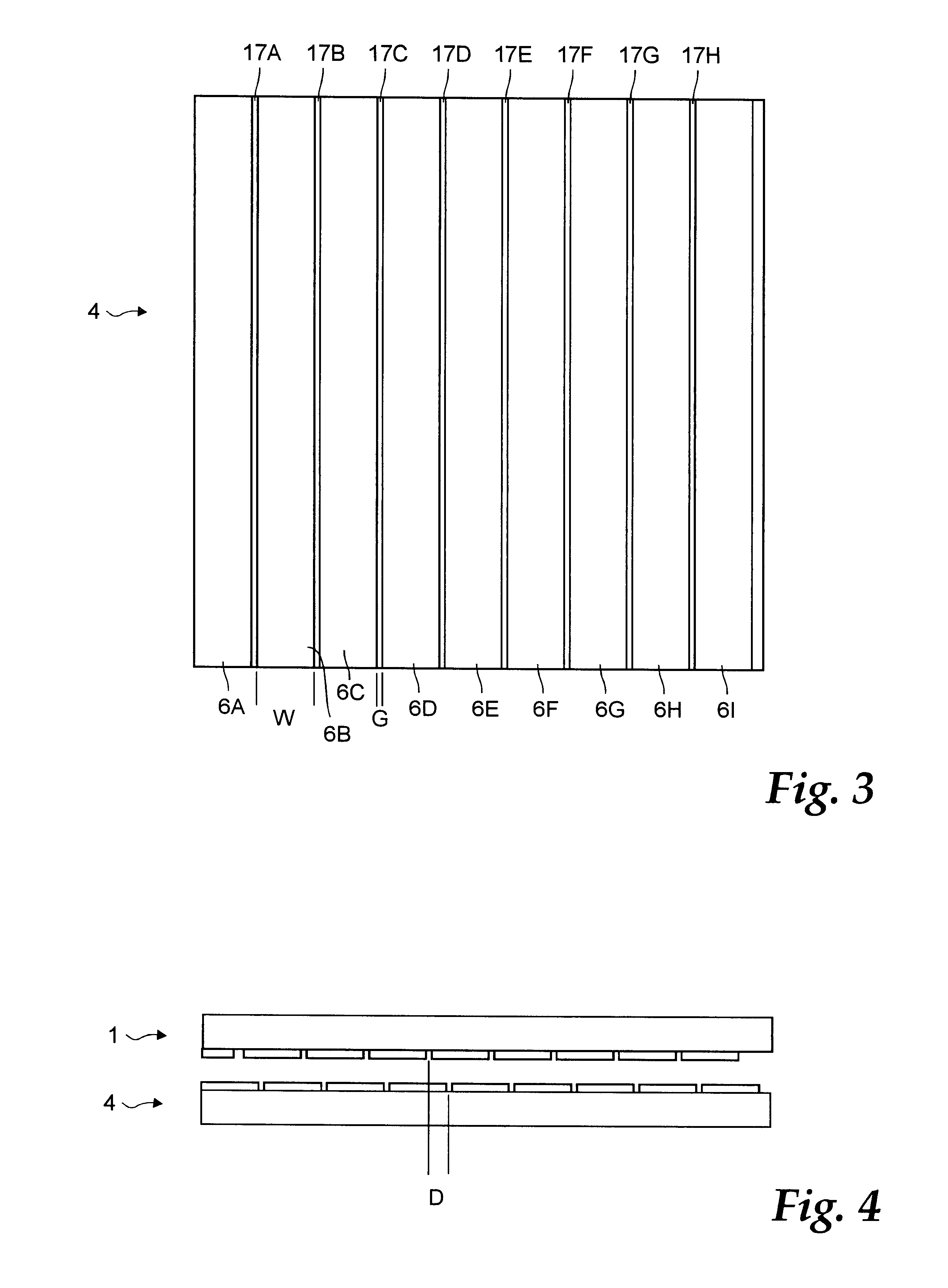
As is illustrated in FIG. 3, wherein a top view of the lower conducting glass 4 of FIG. 1 is shown as an example, electrode areas 6A-I each with a width W of 1 cm are separated by straight gaps 17A-H having a width G of 0,1 mm wide. As is seen in FIGS. 3 and 4, the gaps extend from one edge of the substrate to the other and through the thickness of the conducting layer to electrically disconnect the electrode areas. The gaps are formed by any suitable conventional method, such as laser scribing.

It should be noted that the po...

third embodiment

This third embodiment has the advantage that the metal wires are easily registered due to the guiding action of the gaps.

fourth embodiment

the present invention differs from the first embodiment in that at least one of the conducting glasses 1, 4 has an opaque substrate. Similarly, the transparent insulating plate 61 of the second embodiment above can be formed of an opaque material, such as an opaque glass, plastic or ceramic material.


PUM

PropertyMeasurementUnit
light transparencyaaaaaaaaaa
thicknessaaaaaaaaaa
transparencyaaaaaaaaaa

Abstract

An electrolytic cell assembly, e.g. for use in solar panels, is formed by placing coated metal wires (7,9) between the conducting layers (3,6) of two conducting glasses (1,4), respectively. A pressure force (F) is applied to press the metal wires between the conducting layers and to break the coating of the wires, thereby bringing the metal wires in electrical contact with the conducting layers. The coating protects the wires from harmful contact with an electrolyte inside the cell.

Description

The present invention relates to a method for forming electrochemical cells, including forming electrical connections within such cells.TECHNICAL BACKGROUNDElectrode materials formed by a transparent glass or plastic material substrate coated with a thin transparent layer of conducting material are generally referred to as transparent conductors, conducting glasses or conducting plastics. For reasons of convenience, the term "conducting glass" will be used throughout the present application to indicate both glass and plastic substrates being provided with a conducting layer. It should also be noted that the present invention is not limited to transparent conducting glass, but is useful also in cases wherein the substrate and / or the thin conducting layer is opaque.Furthermore, for reasons of convenience the term "electrochemical cell" will be used throughout the present invention to designate "electrochemical and / or photoelectrochemical cell", such as solar cells, cells in liquid cry...

Claims


Application Information

Patent Timeline
Patent Type & Authority Patents(United States)
IPC IPC(8): H01G9/20H01M14/00H01M6/04H01M2/20H01M6/12H01L31/04H01M50/50
CPCH01G9/2081H01M14/005H01M2/20Y10T29/49002Y02E10/542H01M6/12Y02P70/50H01M50/50
Inventor LINDQUIST, STEN-ERICHAGFELDT, ANDERSLINDSTROM, HENRIKSODERGREN, SVEN
Owner FORSKARPATENT I UPPSALA
Learn More