
Method and device for measuring a distance between a stator and a rotor

a technology of stator and rotor, which is applied in the field of measuring a distance can solve the problems of continuous wear of the sensor during operation, large wear of the sensor during zeroing, and the change in the size of the refining gap between a stator and a rotor during operation, so as to achieve a more reliable and convenient distance determination

Inactive Publication Date: 2003-12-02
CV PROD INC
View PDF10 Cites 8 Cited by
  • Summary
  • Abstract
  • Description
  • Claims
  • Application Information

AI Technical Summary

Benefits of technology

The object of the invention is to make easier and more reliable determination of the distance between the stator and the rotor possible in machines of the type indicated.
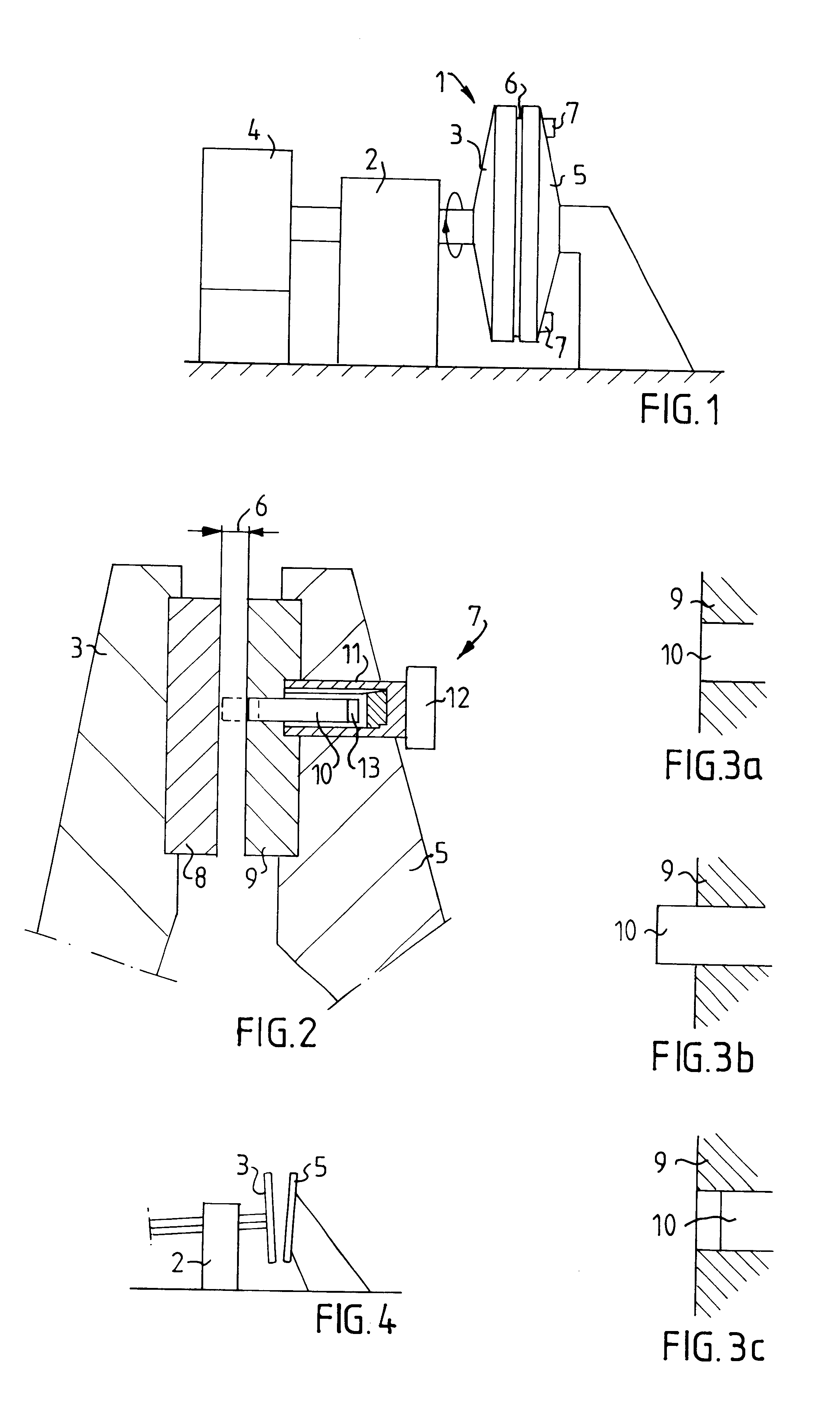
By using at least one sensor mounted movably in the stator, the sensor can be calibrated easily with regard to gain. Moreover, the possibility is afforded of checking the sensor by moving it a certain distance, with the rotor either at a standstill or rotating. For zero calibration, it is no longer necessary to move the rotor axially until contact is made between the refining segments, but it is sufficient to move the sensor into contact with the rotor.
The mobility of the sensor also makes it possible, in the event of contact between the refining segments on the rotor and the stator during operation, to reverse the sensor a little distance from its normal position level with the surface of the refining segment, so that further wear of the sensor is avoided. By using a number of sensors on the stator, it is also possible to measure and control any relative inclination between the stator and the rotor.

Problems solved by technology

In refiners intended for paper pulp production, the size of the refining gap between a stator and a rotor is changed during operation as a consequence of wear on the mutually facing refining segments on the stator and the rotor.
One of the disadvantages of such a procedure is that it can DC used only on machines in which the rotor can be operated very accurately, as otherwise the zeroing wear can be great, and calibration and checking of the sensor can furthermore be carried out only during idle running.
Another disadvantage is that the positioning of the sensor in the surface of the refining segments results in continuous wear of the sensor during operation.

Method used


Image

  • Method and device for measuring a distance between a stator and a rotor
  • Method and device for measuring a distance between a stator and a rotor

Examples


Embodiment Construction

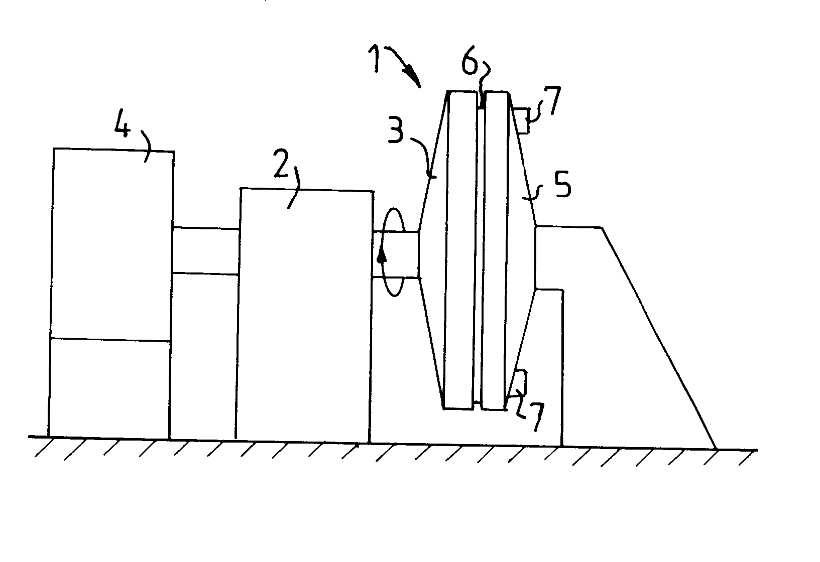
FIG. 1 shows diagrammatically those parts of a machine 1 of the refiner type intended for paper pulp production which are necessary to understand the invention. This machine is provided with a rotor 3 which is mounted rotatably in a stand 2, is driven by a motor 4 and can also be moved axially in the direction towards and away from a stator 5 in order to regulate the size of a refining gap 6 between the rotor 3 and the stator 5. For checking the size of the refining gap 6, at least one sensor arrangement 7, with a sensor of magnetic type which suitably works according to the reluctance principle, is mounted in the stator 5. This type of sensor is well known to the expert in the field. Two or more sensor arrangements 7 can suitably be distributed around the stator 5.

As shown in greater detail in FIG. 2, both the rotor 3 and the stator 5 are provided with refining segments 8, 9 which have a surface suitable for refining paper pulp and are mounted in a suitable number in a ring on the ...


PUM

PropertyMeasurementUnit
diameteraaaaaaaaaa
distanceaaaaaaaaaa
sizeaaaaaaaaaa

Abstract

In a machine which is provided with a stator and an opposite rotor, a sensor of magnetic type, arranged in the stator, for determining the distance between the stator and the rotor can be calibrated by the sensor first being moved relative to the stator into contact with the rotor for zeroing. The sensor is then reversed a predetermined distance, after which the sensor signal can be used for determining the distance between the stator and the rotor. In an arrangement suitable for the purpose, the stator has at least one sensor of magnetic type, which is intended to interact with an opposite surface on the rotor. The sensor is mounted displaceably in the axial direction of the rotor and can be brought into contact with the rotor.

Description

The present invention relates on the one hand to a method for determining distance, and on the other hand to an arrangement for determining distance.PRIOR ARTIn refiners intended for paper pulp production, the size of the refining gap between a stator and a rotor is changed during operation as a consequence of wear on the mutually facing refining segments on the stator and the rotor. For reasons of quality, it is desirable to have good control over the size of the refining gap and to be able to compensate for wear, or to change the size of the refining gap for other reasons. Refiners of this type usually have long operating periods, often several months, or which reason it should be possible to effect monitoring of the size of the refining gap during operation.In order to measure the size of the refining gap, it is customary to use sensors of magnetic type which are positioned in a stationary manner in the stator, with the end surface of the measuring head level with the surface of ...

Claims


Application Information

Patent Timeline
Patent Type & Authority Patents(United States)
IPC IPC(8): B02C7/14B02C7/00D21D1/30D21D1/00G01B7/14G01B7/00
CPCB02C7/14D21D1/002G01B7/14D21D1/30G01N33/343G01N27/02
Inventor ANG.AKERBLOM, BENGT
Owner CV PROD INC
Learn More