Tank for storing gas at high pressure

a gas storage tank and high-pressure technology, applied in the direction of manufacturing tools, refuse collection, container discharging methods, etc., can solve the problems of large size, heavy and expensive storage assemblies, etc., and achieve the effect of significant mass and bulk savings

Inactive Publication Date: 2003-12-09
SN DETUDE & DE CONSTR DE MOTEURS DAVIATION S N E C M A
View PDF13 Cites 21 Cited by
  • Summary
  • Abstract
  • Description
  • Claims
  • Application Information

AI Technical Summary

Benefits of technology

The invention thus proposes a tank for storing gas at high pressure which enables mass and bulk to be reduced significantly compared with prior art tanks for given storage volume. Furthermore, the tank of the invention is of a design which not only optimizes the tank in terms of mass and bulk, but also guarantees that it complies with the safety requirements for this type of storage.
In this way, the coupling means of a tank no longer project therefrom, thus reducing the overall size thereof.
The innermost turn of the coil whose inside face cannot benefit from an adjacent turn compensating the force exerted by the gas pressure is thus reinforced on the inside.
The outermost turn of the coil whose outside face cannot benefit from an adjacent turn compensating the force exerted by the gas pressure is thus reinforced on the outside.
The invention thus provides a method of manufacturing a tank which makes it possible to obtain a tank that is at least as reliable in terms of safety as tanks known in the prior art and which provides significant savings in mass and bulk.

Problems solved by technology

Combining cylinders does indeed serve to reduce one of the dimensions used for storage, for example the height dimension, but it inevitably gives rise to storage assemblies that are heavy and expensive, and that are larger in size with respect to their other dimensions.

Method used


Image

  • Tank for storing gas at high pressure
  • Tank for storing gas at high pressure
  • Tank for storing gas at high pressure

Examples


first embodiment

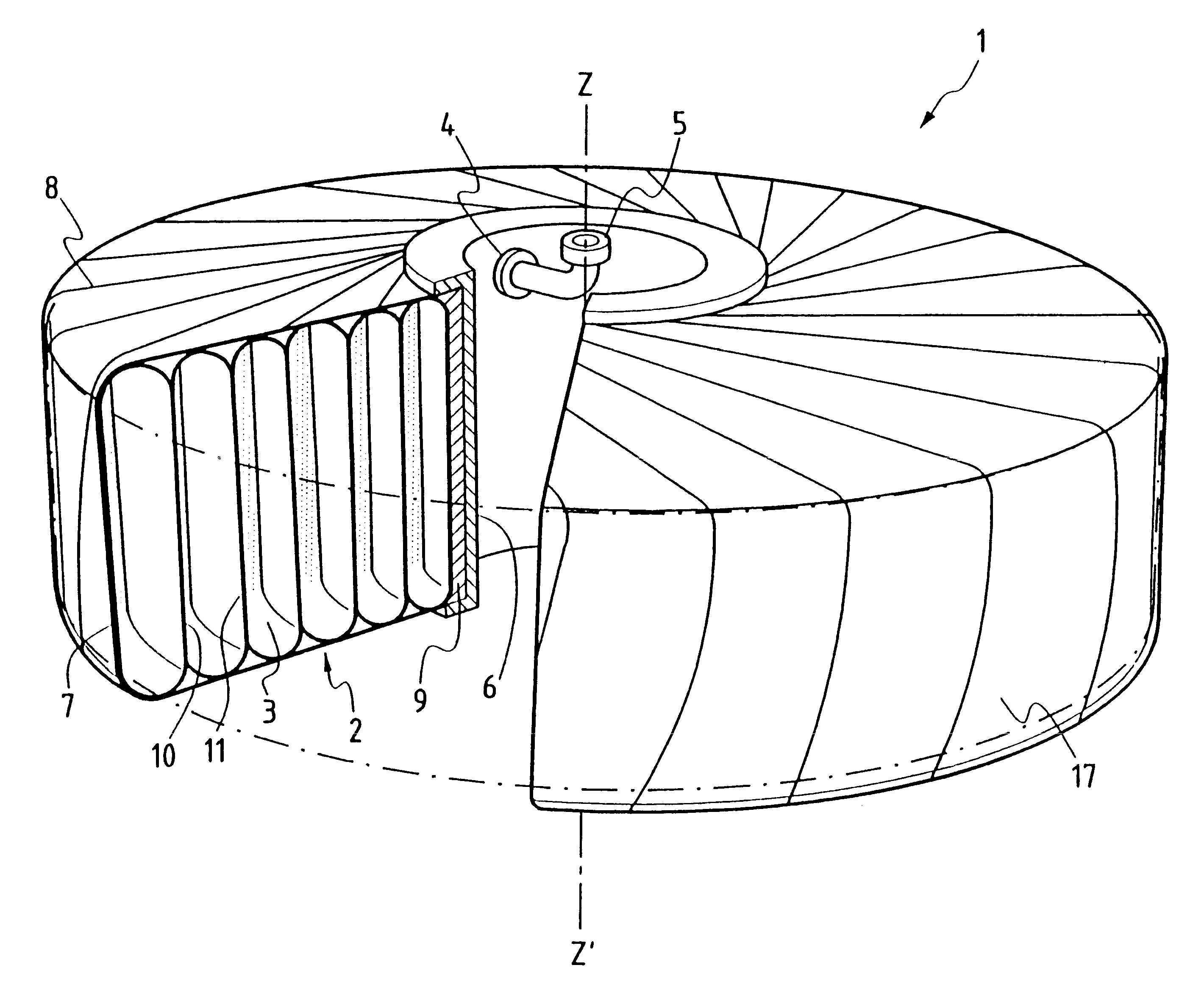
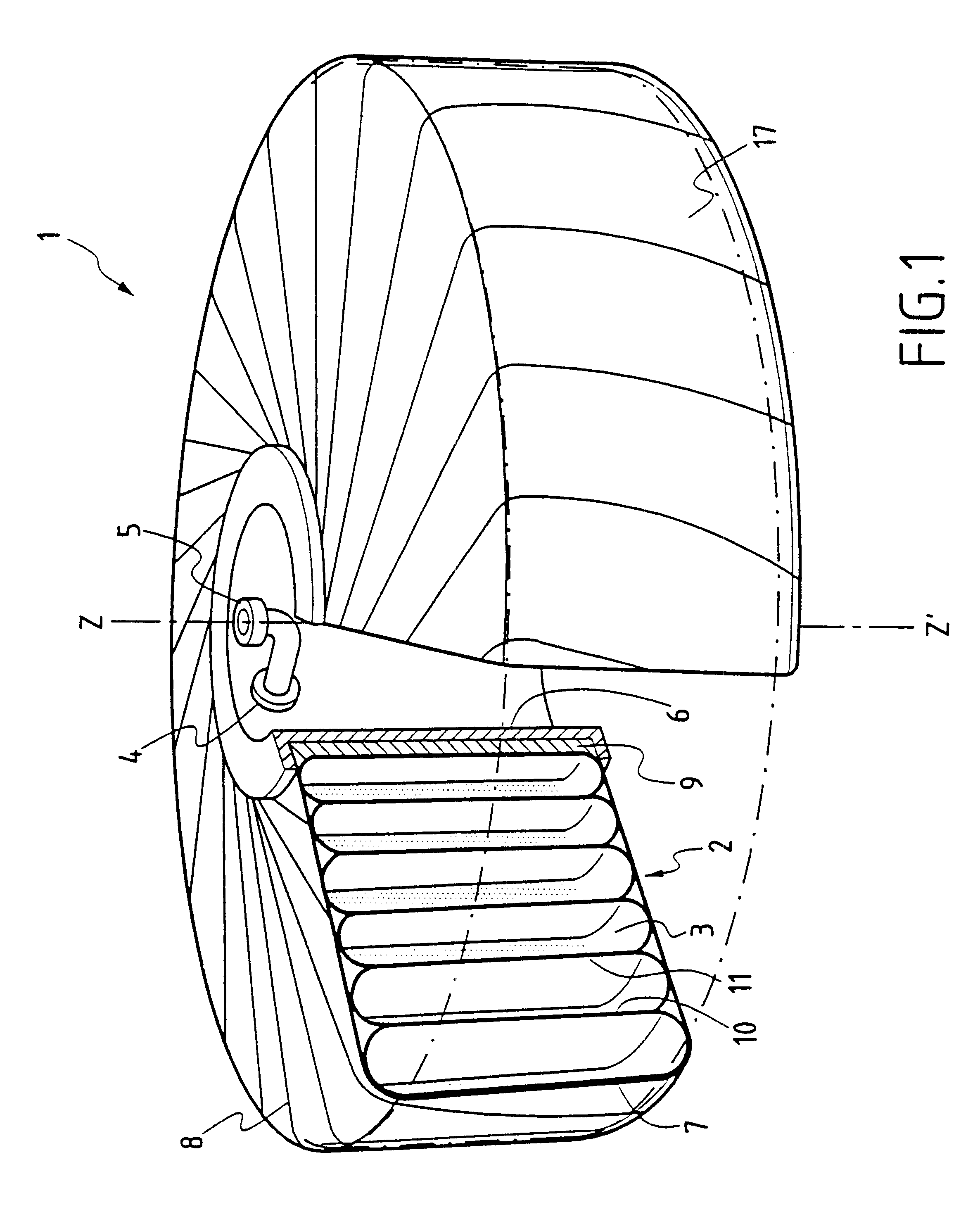
FIG. 1 shows a tank 1 for storing gas at high pressure, and in the invention this tank comprises a gas confinement volume 2 constituted by a spiral coil of a metal duct 3 about an axis ZZ'. The duct 3 has a section that is flat or oblong in shape and it is coiled as a plurality of adjacent turns to enable the turns to bear against one another via their substantially rectilinear elongate portions 10, 11 with the exception of the innermost turn and of the outermost turn each of which has only one of its rectilinear portions bearing against an adjacent turn.

Coiling a duct of flat section so that its turns touch enables the objects of the invention to be achieved, specifically it enables mass, bulk, and cost of the tank to be reduced compared with a conventional tank for storing the same quantity of gas.

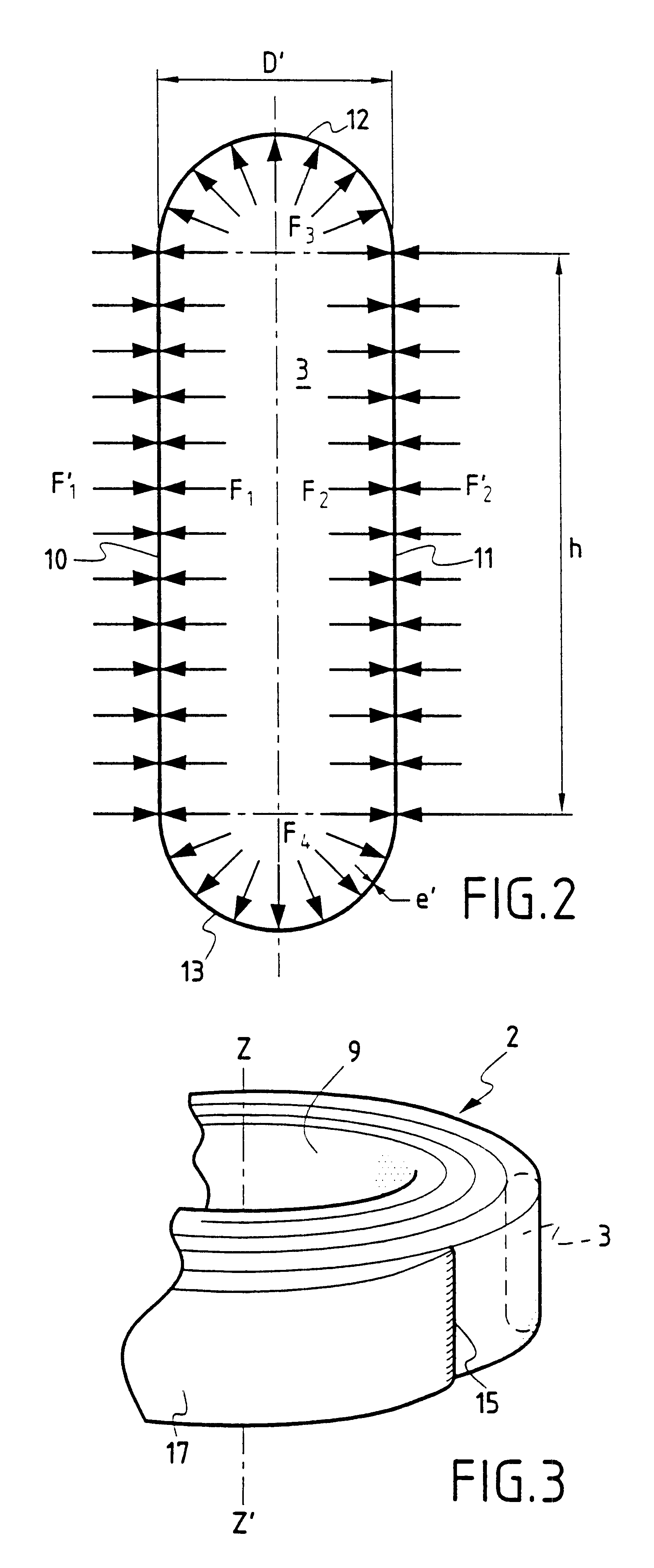
FIG. 2 is a section through the duct 3 showing two rectilinear elongate portions 10, 11 interconnected by curvilinear portions 12, 13. The forces exerted by the gas pressure on the elong...

fourth embodiment

FIG. 9 shows tank 300 of the invention which differs from the preceding embodiments not only in its shape but also in the way the duct is coiled about the axis ZZ'. In the embodiments described with reference to FIGS. 1, 7, and 8, the duct is coiled as a spiral around the axis ZZ' with the elongate portions 10, 11 of adjacent turns extending parallel to the axis ZZ'. This has the effect of coiling the duct around itself and it is the number of turns in the coil that defines the diameter or transverse size of the resulting tank. In different manner, the tank 300 shown in FIG. 9 comprises a duct 303 that is likewise oblong in section, but that is coiled around the axis ZZ' in a helical disposition. In this structural configuration, the coiling of the turns begins at one end 315, e.g. the end that tapers down to a welded tip, and it is coiled upwards about the axis ZZ' to its other end 316 which is fitted with the coupling and communication means 304, 305. In this embodiment, the set o...

fifth embodiment

The fifth embodiment shown in FIG. 11 serves in particular to obtain tanks in the form of compact rectangular parallelepipeds without any empty space in the center of the tank.

Tanks of the invention are well suited to storing gas at pressures that can be of the order of 200 bars, for example, or even higher. Such tanks can be of reduced mass, particularly if they are made of a material such as aluminum.

When a tank of the invention is integrated in a vehicle, it will be observed that from the safety point of view, because of its shape that implements pseudo-partitioning, the effects of a sudden loss of pressure, e.g. due to an impact, are moderated by the inertia of the stored mass. In particular, it should be observed that the tank has considerable capacity for absorbing impact in a plane that contains the large dimension of the tank (plane perpendicular to the axis ZZ' in the embodiments of FIGS. 1, 7, and 8, an axial plane containing the axis ZZ' for the embodiment of FIG. 9, and ...


PUM

PropertyMeasurementUnit
heightaaaaaaaaaa
diameteraaaaaaaaaa
pressuresaaaaaaaaaa

Abstract

The tank for storing gas at high pressure, such as a tank for a vehicle running on gas, comprises a confinement volume accessible via coupling means and defined by a duct disposed in a spiral coil so that the substantially rectilinear main portions of the duct bear against one another. The forces exerted by the pressure of the gas on the main portions of a turn of the duct are then compensated by the forces exerted on the adjacent turns of the duct.

Description

The present invention relates to a tank for storing gas at high pressure, the tank comprising a confinement volume in selective communication with the outside via coupling means. More particularly, the invention relates to tanks that are lightweight and compact for storing gas at high pressure in applications to non-polluting terrestrial vehicles (LNG, H2, LPG, . . . ) or indeed to aircraft or spacecraft.Prior ArtConventional tanks for storing gas at high pressure are known generally to be in the form of cylinders or spheres. Those types of tank used singly or on a rack, occupy a large amount of volume because of their shape and because of the presence of projecting means for coupling and for providing the protection required by regulations (against impact, fire, . . . ). Combining cylinders does indeed serve to reduce one of the dimensions used for storage, for example the height dimension, but it inevitably gives rise to storage assemblies that are heavy and expensive, and that ar...

Claims


Application Information

Patent Timeline
Patent Type & Authority Patents(United States)
IPC IPC(8): F17C1/00B21D51/24
CPCF17C1/00Y10T29/49391F17C2201/0138F17C2201/0157F17C2201/0171F17C2201/056F17C2203/012F17C2203/0617F17C2203/0624F17C2203/0646F17C2203/0663F17C2205/0323F17C2209/2154F17C2209/221F17C2209/232F17C2221/012F17C2221/033F17C2221/035F17C2223/0123F17C2223/036F17C2260/012F17C2260/018F17C2270/0168F17C2270/0189F17C2270/0194Y02E60/321Y10S220/13F17C2201/0133Y02E60/32Y10T137/4824
Inventor GARCEAU, PATRICK
Owner SN DETUDE & DE CONSTR DE MOTEURS DAVIATION S N E C M A
Why Eureka
Try Eureka