Image display generator for a head-up display

a generator and display technology, applied in the direction of static indicating devices, lighting and heating devices, instruments, etc., can solve the problems of undue heat generation of crts from the source,

Inactive Publication Date: 2003-12-09
INNOVATIVE SOLUTIONS & SUPPORT
View PDF14 Cites 92 Cited by
  • Summary
  • Abstract
  • Description
  • Claims
  • Application Information

AI Technical Summary

Problems solved by technology

Such CRTs also generate undue amounts of heat that must be dissipated from the source.

Method used


Image

  • Image display generator for a head-up display
  • Image display generator for a head-up display
  • Image display generator for a head-up display

Examples


Embodiment Construction

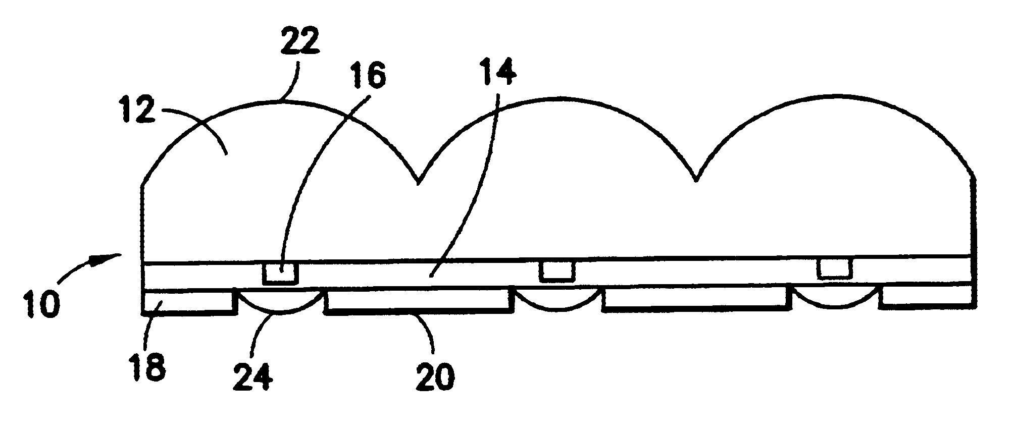
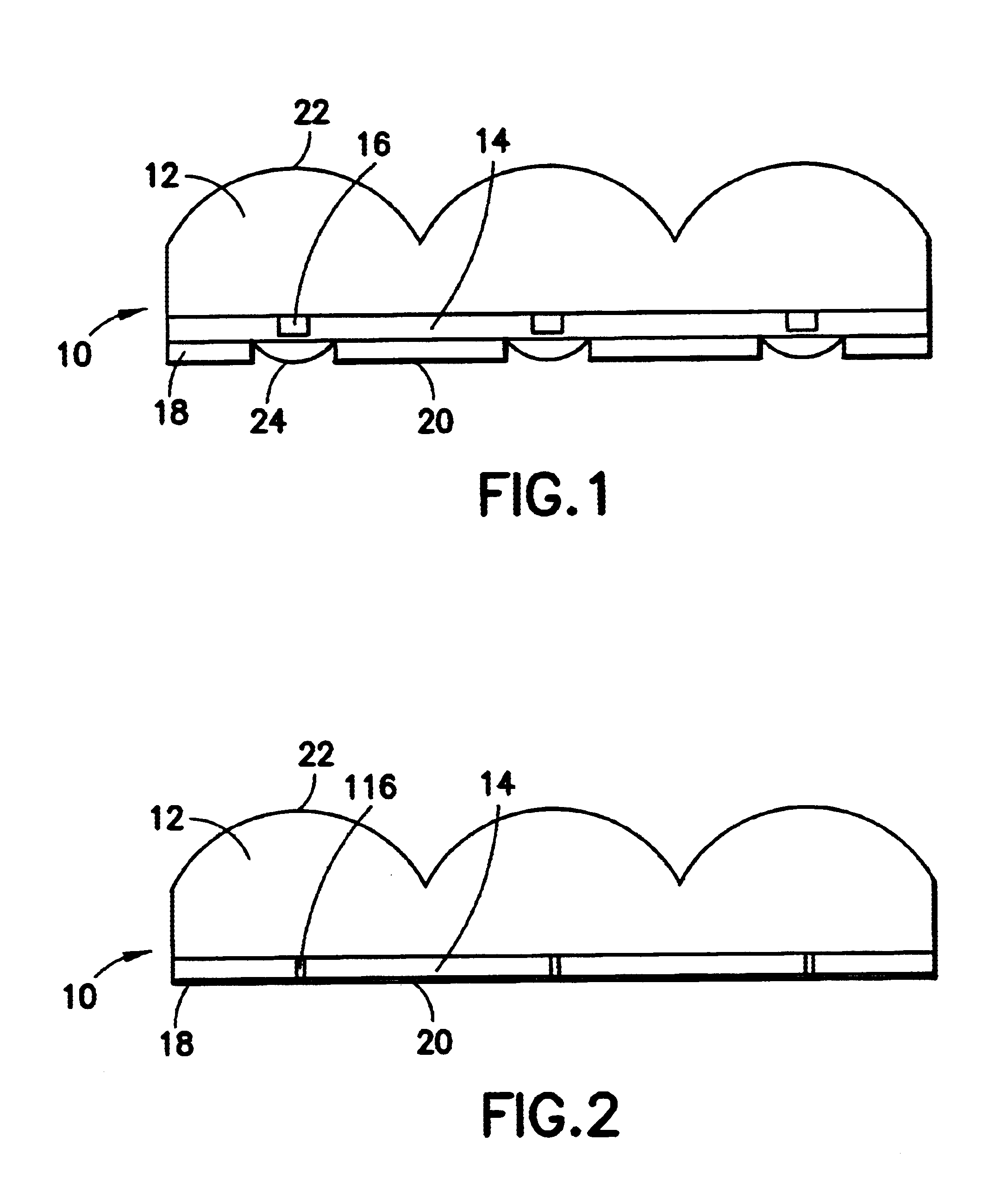
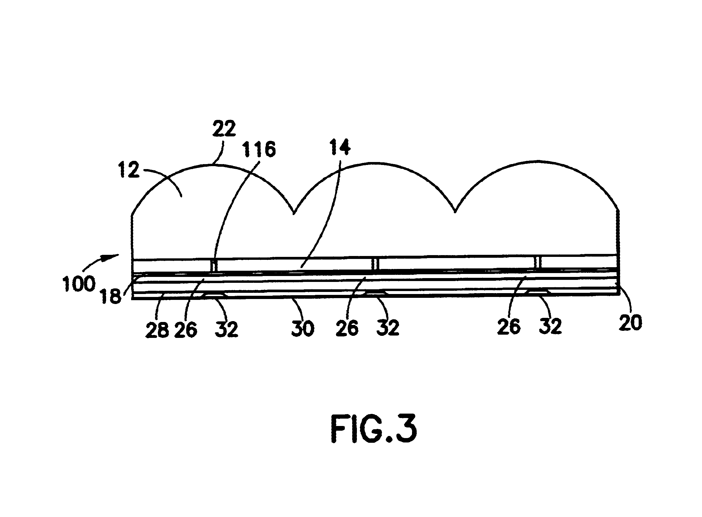
Manufacture of a display generator 10 in accordance with the invention, as depicted in FIG. 1, begins with a sheet of transparent, preferably clear, glass-like material having a relatively high refractive index and a substantially constant and known thickness. A suitable and currently preferred material is Sapphire, and Sapphire sheets are commercially available. A thin layer of semiconductor material 14 such as Gallium Arsenide (GaAs) is then grown or deposited in a known manner on one surface of the Sapphire sheet 12. LED (light emitting diode) junctions 16, and (in preferred forms of the invention) associated or support circuitry, and interconnects therefor, are diffused into the Gallium Arsenide 14 to form the actuatable LED light emitters. An insulating passivation layer such as of Silicon Dioxide (SiO.sub.2) is then layered or deposited on the Gallium Arsenide layer which contains the LEDs and interconnects and optional support circuitry.

A thin layer of reflective material 20,...


PUM


Abstract

An image display generator for use in a head-up display includes an array of light emitting devices such as LEDs or VCSELs formed on a semiconductor layer deposited on one surface of a glass like, e.g. Sapphire, sheet in which a plurality of lenses are formed on the opposite surface with each lens aligned with a respective one of the LEDs or VCSELs. A layer of transparent insulating material is disposed over the semiconductor layer and is coated with a reflecting material. Light emitted by the LEDs is directly incident onto respective over the lenses and is indirectly reflected onto the lenses by the reflecting material.

Description

1. Field of the InventionThe present invention is directed to an image display generator or projector for a head-up display, and more particularly to an image display generator comprised of a plurality of light emitting diodes (LEDs) which are individually selectively activatable to emit light for collectively defining or forming an image.2. Description of the Related ArtIn current implementations of head-up displays, such as those used in advanced aircraft, an image projector--which may, for example, comprise a cathode ray tube to which the image to be projected is electronically fed--outputs a visually-perceptible image. The image output from the projector is then directed through a diffractive optics lens to collimate the image, after which the collimated image is reflected, by one or a series of full or partial reflectors, into the pilot's view or sight path for viewing of the projected image in overlaid concurrency with objects located outside of the cockpit windshield or windo...

Claims


Application Information

Patent Timeline
Patent Type & Authority Patents(United States)
IPC IPC(8): G02B27/01G02B27/00G02B3/00H01L27/15H01L33/00H01L33/08H01L33/44H01L33/48H01L33/58H01L33/60H01L33/64
CPCG02B27/01G02B27/0101H01L27/153G02B2027/0118G02F1/1335
Inventor HEDRICK, GEOFFREY S. M.
Owner INNOVATIVE SOLUTIONS & SUPPORT
Why Eureka
Try Eureka