Bi-directional vector rotator

a rotator and bi-directional technology, applied in the field of data transmission, can solve the problems of increasing the complexity and cost of the device, and needing a single complex carrier signal

Inactive Publication Date: 2003-12-09
QUALCOMM INC
View PDF8 Cites 10 Cited by
  • Summary
  • Abstract
  • Description
  • Claims
  • Application Information

AI Technical Summary

Problems solved by technology

The additional vector rotator typically equates to additional hardware, which increases the complexity and costs of the device.
Moreover, the carrier signal generator typically needs to be modified to provide a second phase for the second vector rotator, thereby further increasing the complexity of the design.
Moreover, only one complex carrier signal is needed by the bi-directional vector rotator instead of two for the conventional design.

Method used


Image

  • Bi-directional vector rotator
  • Bi-directional vector rotator
  • Bi-directional vector rotator

Examples


Embodiment Construction

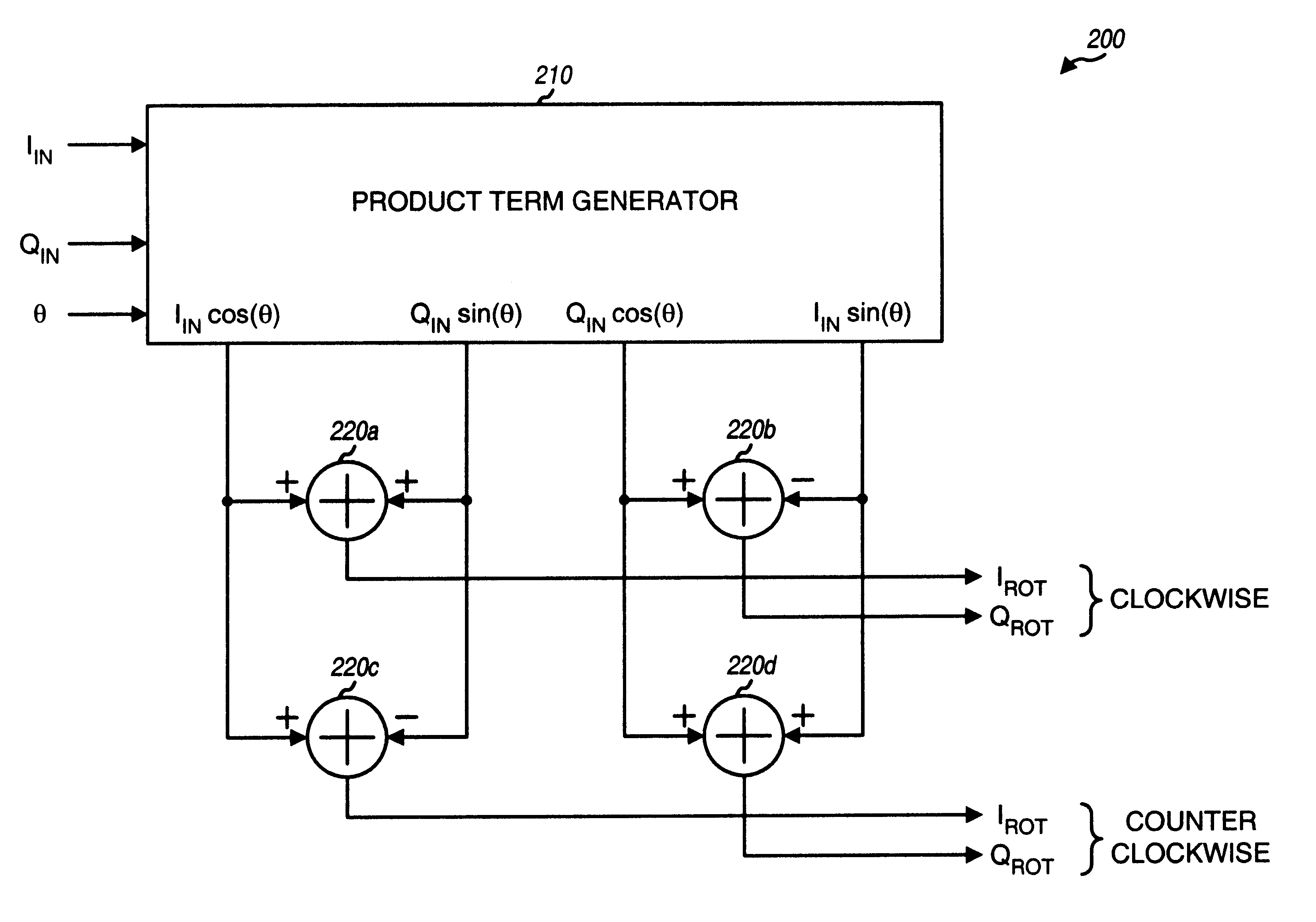
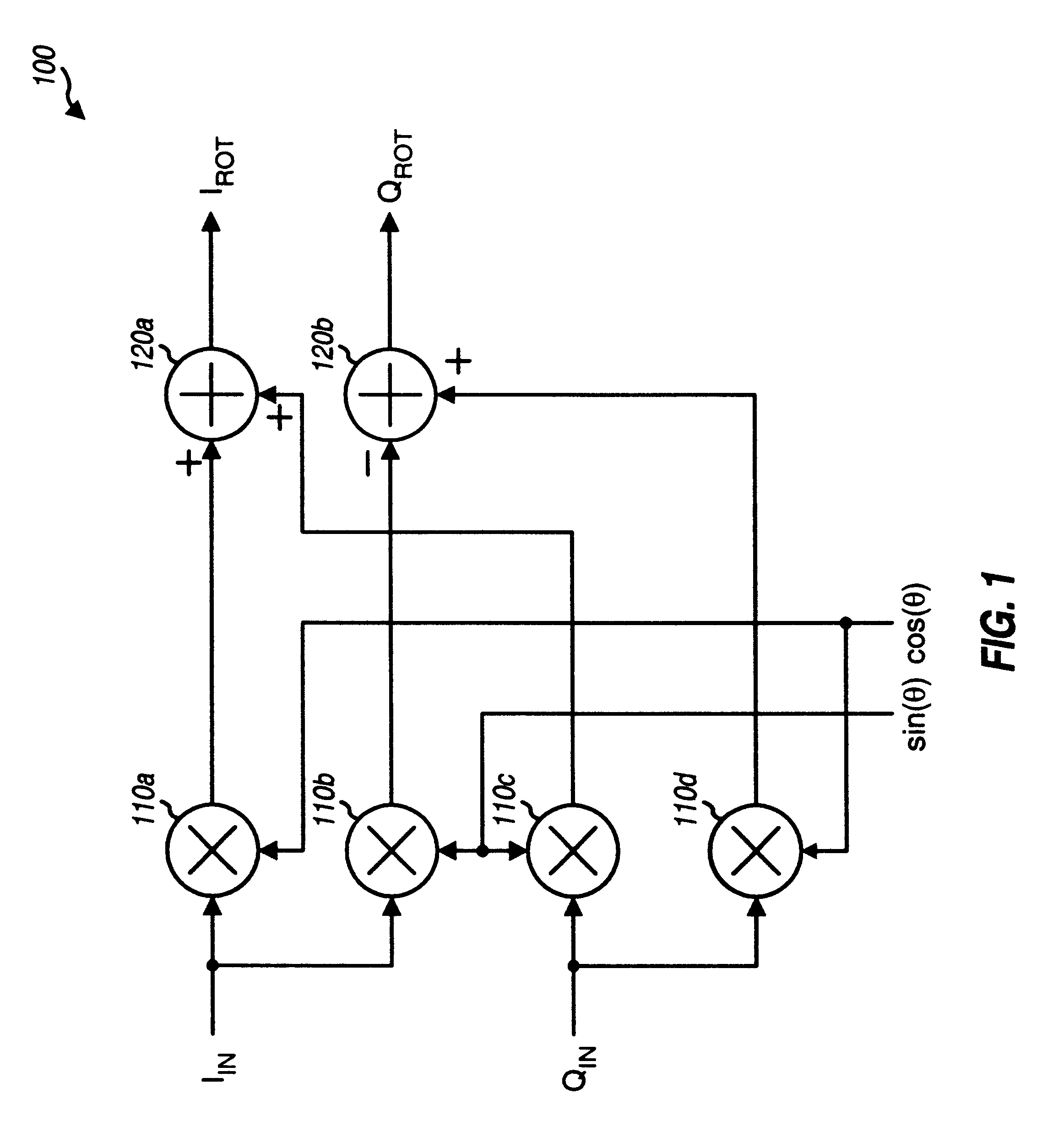
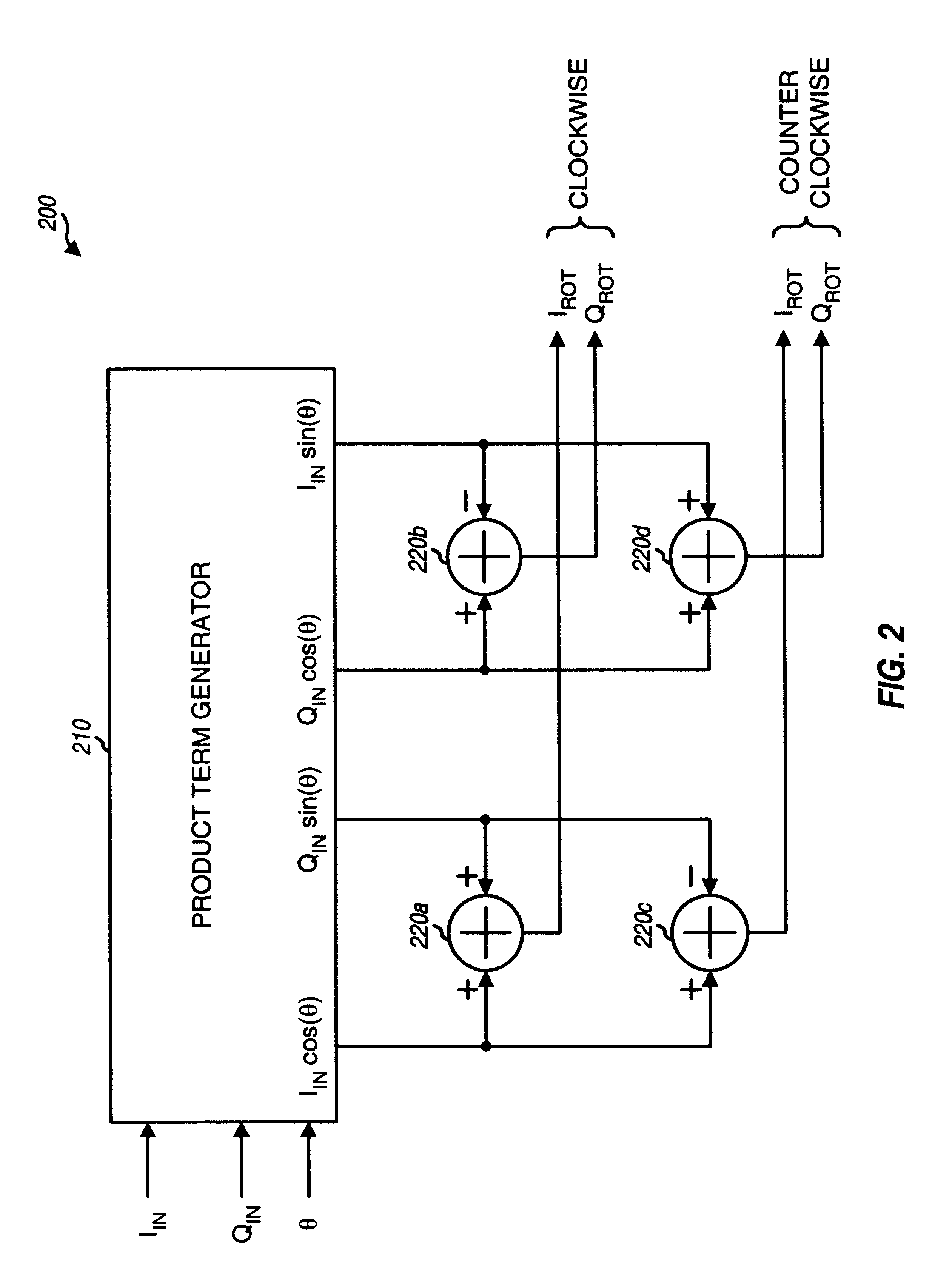
FIG. 1 is a block diagram of a conventional vector rotator 100 that can be used to rotate the phase of the complex input samples in one direction. The complex input samples comprise the inphase (I.sub.IN) and quadrature (Q.sub.IN) samples, and each pair of I.sub.IN and Q.sub.IN samples can be viewed as a complex vector represented as I.sub.IN +jQ.sub.IN. Phase rotation in the clockwise direction by an angle .theta. is mathematically equivalent to multiplication of the complex vector by the term e.sup.-j.theta.. The phase rotated vector, I.sub.ROT.sup.cw +jQ.sub.ROT.sup.cw, for the clockwise rotation can be expressed as: ##EQU1##

where

I.sub.ROT.sup.cw =I.sub.IN cos .theta.+Q.sub.IN sin .theta.,

and

Q.sub.ROT.sup.cw =Q.sub.IN cos .theta.-I.sub.IN sin .theta.,

which is equivalent to

I.sub.ROT.sup.cw =I.sub.IN cos .theta.+Q.sub.IN cos(90-.theta.),

and

Q.sub.ROT.sup.cw =Q.sub.IN cos .theta.-I.sub.IN cos(90-.theta.). Eq (2)

Similarly, phase rotation in the counter clockwise direction by an angle ...


PUM


Abstract

A bi-directional vector rotator that can be used to provide outputs having phases that are rotated in clockwise and counter clockwise directions relative to that of the input signal. The bi-directional vector rotator includes a product term generator that receives a complex input and a complex carrier signal and generates product terms. Combiners then selectively combine the product terms to generate the outputs. By sharing the same product term generator for both clockwise and counter clockwise phase rotations, the bi-directional vector rotator can be implemented using less circuitry than that for a conventional design employing two uni-directional vector rotators. Moreover, only one complex carrier signal is needed by the bi-directional vector rotator instead of two for the conventional design. Further simplification in the design of the bi-directional vector rotator can be achieved by selecting the proper sampling rate for the complex input. The bi-directional vector rotator can be advantageously used in a receiver device, and is especially efficient in demodulating a multi-carrier signal having multiple (e.g., three) modulated signals.

Description

I. Field of the InventionThe present invention relates to data transmissions. More particularly, the present invention relates to a bi-directional vector rotator capable of rotating the phase of a signal in clockwise and counter clockwise directions.II. Description of the Related ArtIn a typical digital communications system, data is processed at a transmitter device, modulated using a particular modulation scheme, filtered, amplified, and transmitted to one or more receiver devices. The modulation scheme can be M-ary phase shift keying (e.g., BPSK, QPSK, OQPSK, and so on), M-ary quadrature amplitude modulation (i.e., M-QAM), or some other scheme. At a receiver device, the modulated signal is received, conditioned, demodulated, and processed to recover the transmitted data.Depending on the particular modulation scheme used at the transmitter device, the demodulation typically includes converting the received modulated signal into inphase (I) and quadrature (Q) signals that are furth...

Claims


Application Information

Patent Timeline
Patent Type & Authority Patents(United States)
IPC IPC(8): H04L27/28H04L27/00H04L27/26
CPCH04L27/28H04L27/0014
Inventor KANG, INYUP
Owner QUALCOMM INC
Why Eureka
Try Eureka