Report cover with clamping slide bar

a slide bar and clamping technology, applied in the field of locking slide bars or clasps, can solve the problems of negative interlocking connection, system still has several problems, and the grip force is often inadequate to secure the grip

Inactive Publication Date: 2003-12-16
ONG BON S
View PDF7 Cites 16 Cited by
  • Summary
  • Abstract
  • Description
  • Claims
  • Application Information

AI Technical Summary

Benefits of technology

The channel-shaped clasp is of uniform cross section throughout and is formed with a pair of jaws joined together and projecting outwardly from their junction to form distal tips that define a gap therebetween. The jaws are oriented in opposition relative to each other. The distal tips are directed toward each other to form an angle therebetween of at least about forty-five degrees. The binding edge of the stack, the narrow margin binding panel, and the margin portion of the back cover panel are inserted in between the jaws with the remainder of the stack and document cover projecting through the gap so that the distal tip of one of the jaws is engaged with the narrow margin binding panel to restrict relative movement between the clasp and the stack in a direction perpendicular to the binding edge.

Problems solved by technology

A major problem with conventional slide grips or slide bars of this type is that the gripping force is frequently inadequate to secure the grip on the binding edge of the stack of papers.
However, this system provides no positive interlocking connection between the slide bar and the report cover so that the report cover grip still slides free from the cover when the report is opened.
However, this system still has several problems.
As a consequence, the material can fail at the fold line and the tabs will separate from the remaining structure of the cover as generally circular die cut punch outs.
While this system works quite successfully, it's still involves the necessary step of securing the binder to the stack of papers by means of fasteners, such as staples.
Where many copies of such documents are required, this extra step adds considerably to the time and expense involved in preparing bound reports and other documents for distribution.

Method used


Image

  • Report cover with clamping slide bar
  • Report cover with clamping slide bar
  • Report cover with clamping slide bar

Examples


Embodiment Construction

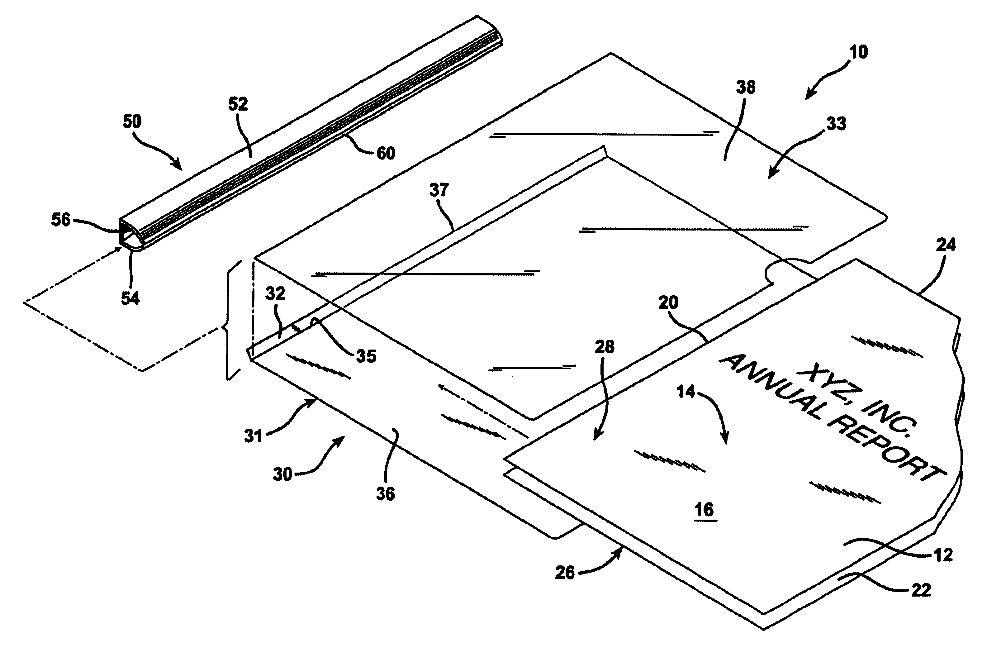
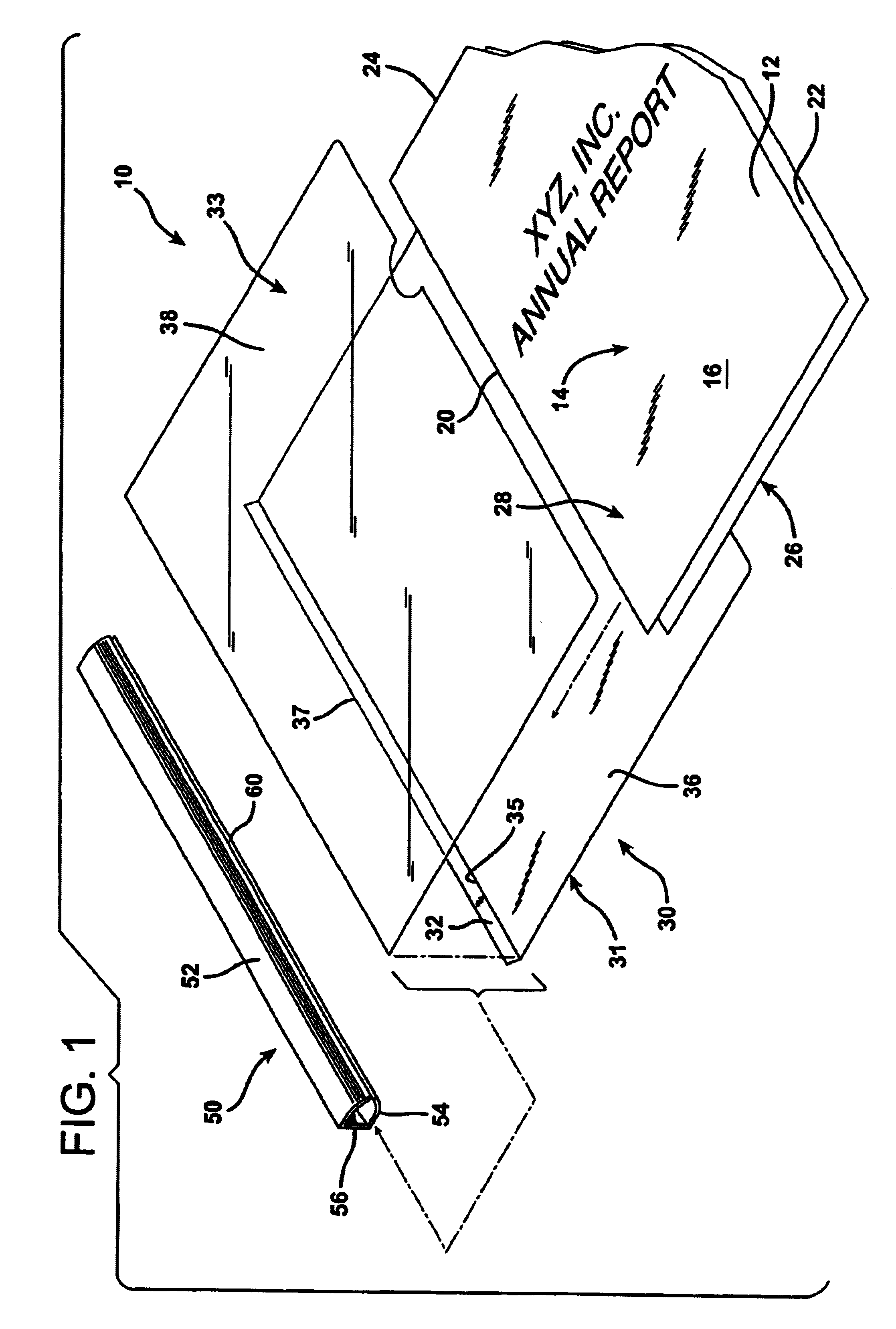
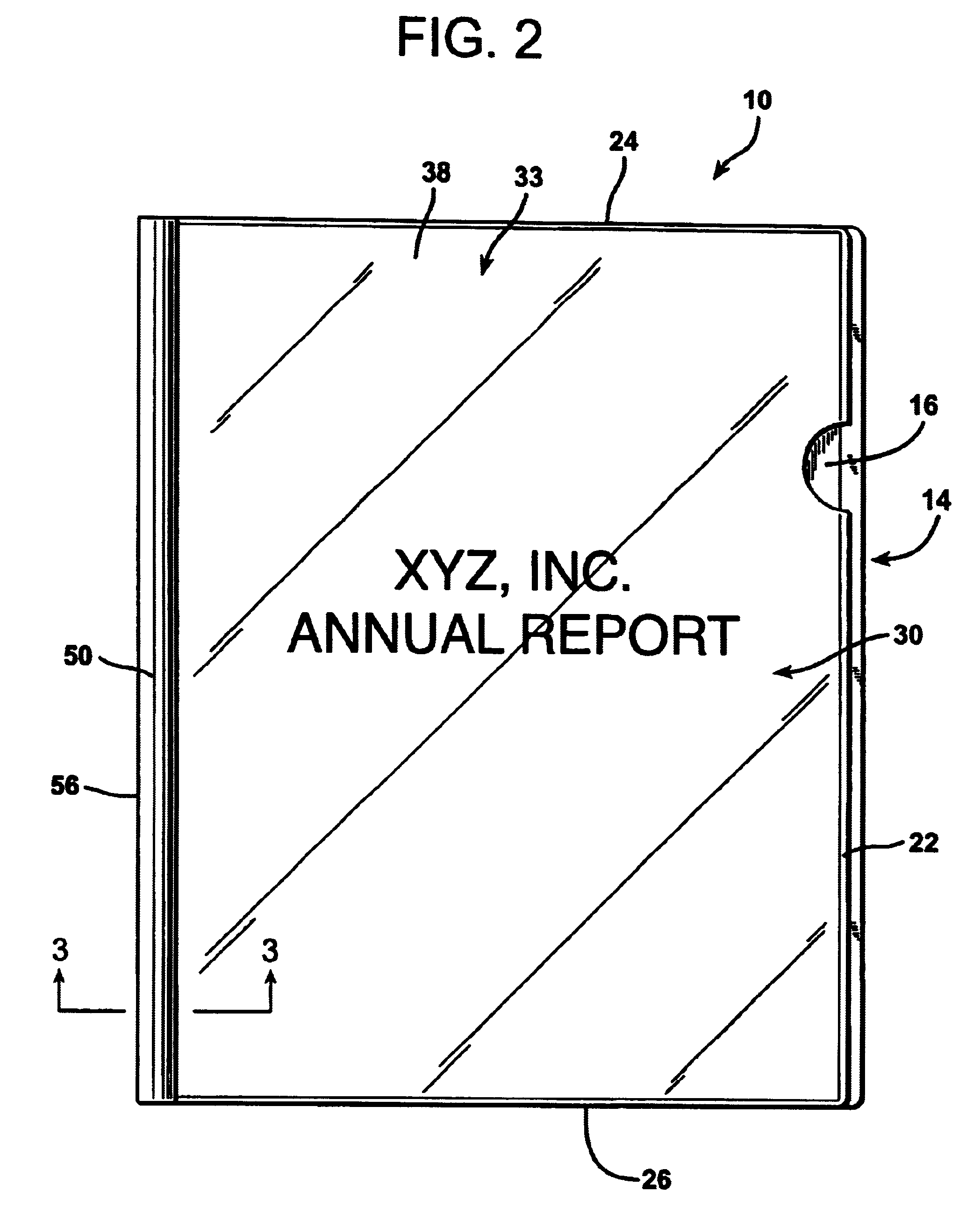
FIGS. 1, 2, and 3 illustrate the combination of the invention generally at 10. The combination 10 is comprised of a plurality of rectangular sheets of paper 12 disposed one atop another to form a stack of papers indicated generally at 14. The paper sheets 12 may have, for example, a width of eight and one-half inches and a length of eleven inches. The paper stack 14 has a top sheet 16 and a bottom sheet 18. For simplicity of illustration of the stack of papers 14 is shown with only a top sheet 16 and bottom sheet 18, although there may be a very considerable number of additional sheets 12 interposed therebetween.

The stack of papers 14 defines a binding edge indicated at 20 and an opposite edge 22 which is parallel to the binding edge 20. The paper stack 14 also has an upper edge 24 and an opposite lower edge 26. The stack 14 also defines a narrow binding margin 28 which may, for example, be about one-half an inch in width. The binding margin 28 is adjacent to the binding edge 20 of ...


PUM


Abstract

A document formed of a stack of papers bound at the spine is equipped with a slide bar that achieves locking engagement with a document cover formed of a plurality of sheets of material. The sheets of document cover material are joined to each other at a binding margin. The sheet of cover material that passes around the spine of the cover forms a back cover beneath the stack of papers and a narrow, margin panel or strip that overlies the adjacent edge of the other sheet of binding material, which forms a front cover. The slide bar has a pair of jaws that terminate in distal tips that face each other at an angle of least forty-five degrees across a gap defined between the distal tips of the jaws. The slide bar is inserted onto the binding edge of the stack of papers and the cover encompassing them in a direction parallel to the binding edge from either the top or bottom end of the stack. The narrow margin panel atop the binding edge margin or the stack of papers fits within and is captured by the distal tip of one of the clasp jaws adjacent thereto throughout its length and throughout the length of the binding edge of the stack of papers. The capture of the narrow binding margin panel by the distal tip of the clasp jaw engaged at the junction between the sheets of the material forming the binder prevents the slide bar from being pulled laterally off of the binding edge of the stack.

Description

1. Field of the InventionThe present invention relates to a locking slide bar or clasp of the type used to form a stiff spine for reports, sales or marketing presentations, and other stacks of paper assembled and bound together.2. Description of the Prior ArtPlastic spines or slide bars for use in gripping the binding edges of stacks of papers together, such as reports, proposals, briefs, and other stacks of documents fastened together along a common edge have been manufactured for many years. Conventional report cover grips or slide bars of this type are manufactured as extruded plastic structures of uniform cross section throughout. Conventional slide grips are formed with a pair of jaws joined together at a common base and forming an open slot or gap therebetween. The jaws are longitudinally elongated so as to extend the entire length of the binding edge of the stack of papers. The gap between the jaws is narrow enough so that they must be forced apart slightly to accommodate the...

Claims


Application Information

Patent Timeline
Patent Type & Authority Patents(United States)
IPC IPC(8): B42F9/00
CPCB42F9/008
Inventor ONG, BON S.
Owner ONG BON S
Why Eureka
Try Eureka