

Pointing device
a pointing device and magnetic sensor technology, applied in the direction of mechanical control devices, manual control with single controlling member, instruments, etc., can solve the problems of increasing the height of the device, increasing the number of parts, and large cost of the magnetic sensor
- Summary
- Abstract
- Description
- Claims
- Application Information
AI Technical Summary
Benefits of technology
Problems solved by technology
Method used
Image

Examples
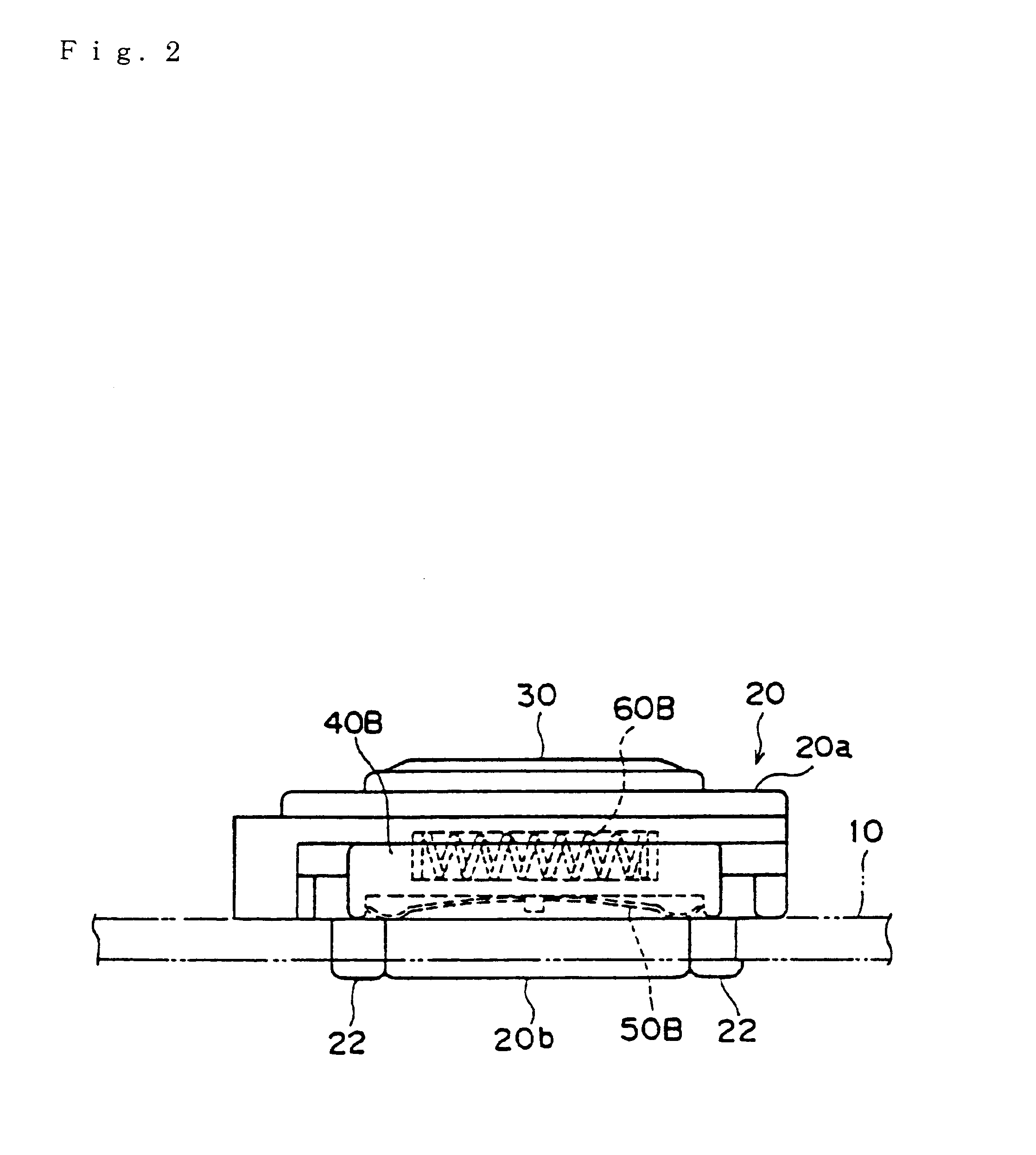
case 20b
The lower case 20b has a body portion 27 formed of a substantially square shallow container and four connecting portions 28, 28, . . . overhanging outward from four corner portions of the body portion 27 and circular through holes 29 in which the corresponding connecting portions 22 of the upper case 20a are respectively press-fitted are respectively formed at the respective connecting portions 28 as shown in FIGS. 8 and 9.
By pushing the connecting portions 22, 22, . . . of the upper case 20a into the through holes 29, 29, . . . of the lower case 20b, the body portion 27 of the lower case 20b is connected to a lower portion of the body portion 21 of the upper case 20a with a small gap maintained therebetween. In this state, respective tip end portions of the connecting portions 22, 22, . . . project below the connecting portions 28, 28, . . . . By inserting the connecting portions 22, 22, . . . into mounting holes formed on the mounting substrate 10, the case 20 is fixed onto the mo...
PUM
 Abstract
Description
Claims
Application Information