
Fiber optic cable winding tool

a fiber optic cable and tool technology, applied in the field of communication, can solve the problems of easy damage to glass fibers used in such cables, further heightened problems, and damage to the communication medium housed within the cabl

Inactive Publication Date: 2003-12-30
STOCKERYALE
View PDF13 Cites 91 Cited by
  • Summary
  • Abstract
  • Description
  • Claims
  • Application Information

AI Technical Summary

Problems solved by technology

However, it is a problem in the field of communication cable installation to provide accurate predetermined lengths of communication cables without damaging the communication cables by the provision of tight bends, or inappropriate use of fasteners, or inadequate support to the communication cables.
In all of these applications, the minimum radius of curvature of the communication cable is well defined, and bending the communication cable in a tighter bend can cause damage to the communication medium housed within the cable.
This problem is further heightened when fiber optic cables are used.
Glass fibers used in such cables are easily damaged when bent too sharply and require a minimum bend radius to operate within required performance specifications.
Damaged fiber optic cables may lead to a reduction in the signal transmission quality of the cables.
If the extra lengths of fiber optic cables are not stored, then they are susceptible to damage since they will freely hang in the equipment and may be pulled, snagged, or bent beyond their minimum bend radii.
The close tolerances in such packages make installation and removal of pre-spooled fiber optic cables very difficult.
Furthermore, the device utilizing the fiber spool often needs a specific length of optical fiber (e.g. the EDFA typically uses a predetermined length of Erbium doped fiber to perform the amplification).
Unfortunately, conventional fiber optic cable spoolers require a different, dedicated reel for each diameter desired.
Furthermore, it is very difficult to remove spooled fiber optic cables from conventional spoolers, without damaging or destroying the fiber optic cable.

Method used


Image

  • Fiber optic cable winding tool
  • Fiber optic cable winding tool
  • Fiber optic cable winding tool

Examples


second embodiment

the fiber optic cable winding tool of the present invention is illustrated in FIGS. 6-10, and shown generally as reference numeral 200. Fiber optic cable winding tool 200 includes a pair of concentric disks 201, 202 capable of rotating relative to each other. Disk 201 has four quarter-circular spools (hubs, jaws, reels, etc.) 204 moveably attached thereto with four T-shaped slide carriages 206. Each spool 204 may attach to its corresponding T-shaped slide carriage 206 via various connection mechanisms. For example, each spool 204 may connect to its corresponding T-shaped slide carriage 206 with an adhesive, glue, double-sided tape, nuts and bolts, screws, etc. As shown in FIG. 6, however, each spool 204 may be integrally formed with its corresponding T-shaped slide carriage 206.

Each T-shaped slide carriage 206 may slidably move towards and away from the other slide cartridges 206 within a corresponding T-shaped slot 207 formed in disk 201 and which radially extends away from the cen...

third embodiment

the fiber optic cable winding tool of the present invention is illustrated in FIGS. 11-14, and shown generally as reference numeral 300. Fiber optic cable winding tool 300 includes four quarter-circular spools (hubs, jaws, reels, etc.) 302 moveably attached together with a resilient ring 304, such as a resilient 0-ring. Each spool 302 may have an opening 311 provided therein for receiving and retaining one end of the fiber optic cable to be wound thereon before the winding is begun. A central disk-shaped base (hub, drive dog, etc.) 306 having four radial guides (translation spokes, etc.) 308 may be provided centrally to each spool 302. Each spool 302 includes a guide slot 310 that slidably receives a corresponding radial guide 308. Resilient ring 304 inwardly biases each spool 302 onto its corresponding radial guide 308, retaining spools 302 on drive dog 306. As best seen in FIG. 12, each spool 302 contains a slot 312 that receives resilient ring 304 therein, and further includes a ...


PUM

PropertyMeasurementUnit
Diameteraaaaaaaaaa
Shapeaaaaaaaaaa
Radiusaaaaaaaaaa

Abstract

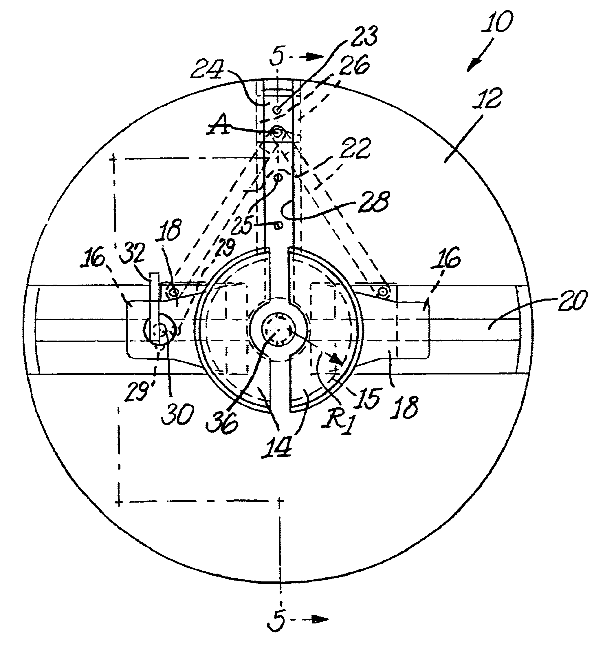
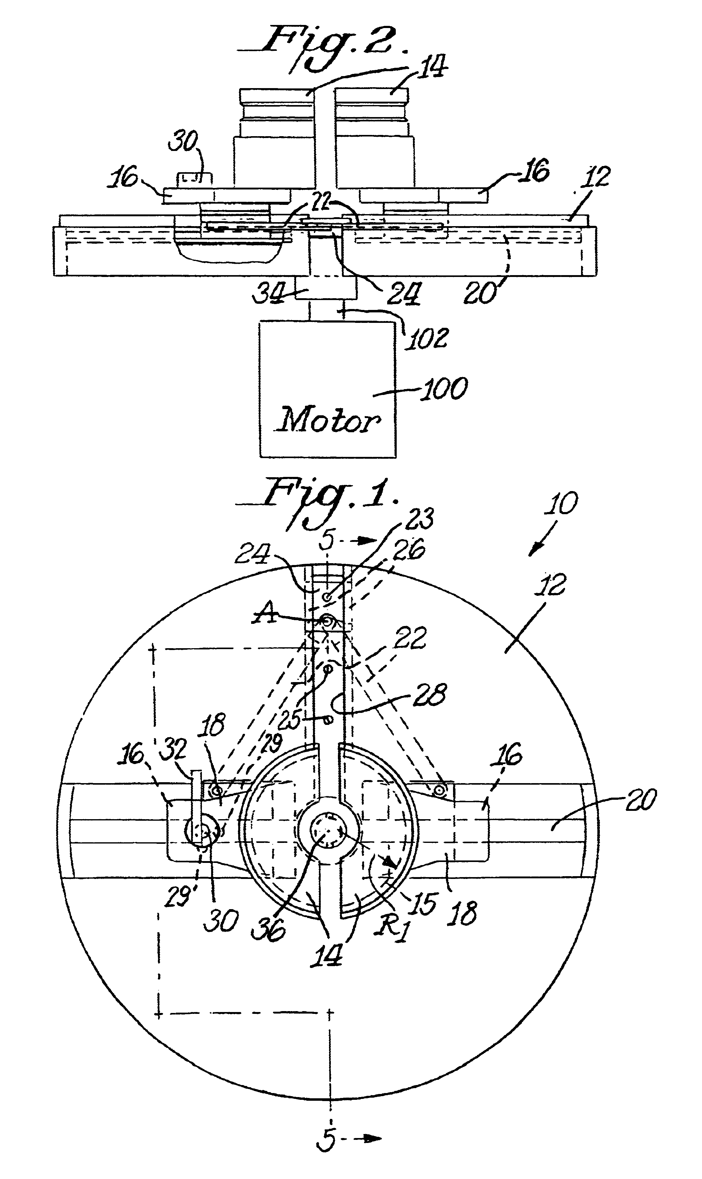
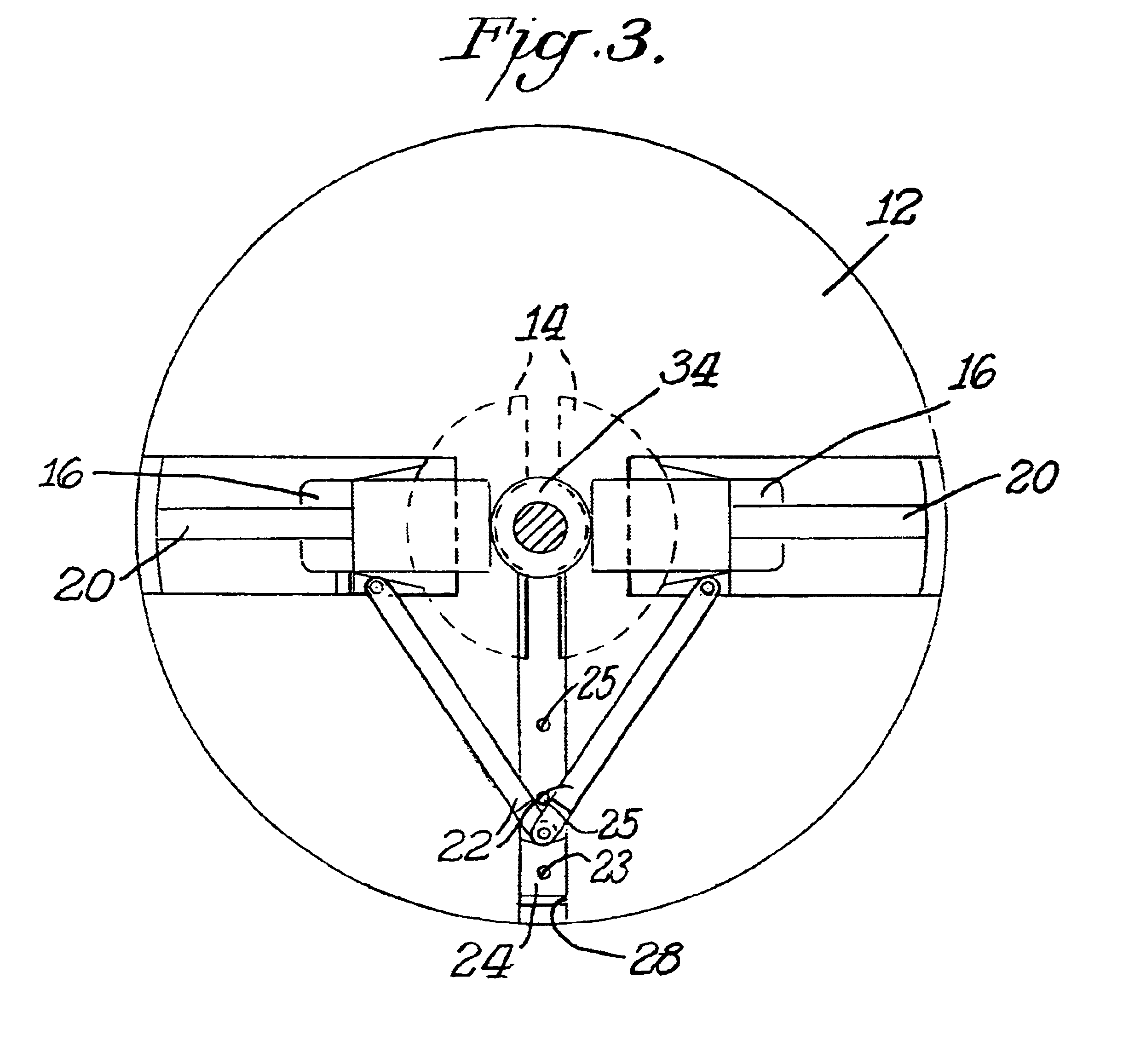
A fiber optic cable winding tool having a disk-shaped base and a pair of semi-circular spools slidably mounted on the base. The spools are radially adjustable toward and from the central axis of the base by providing the spools on rails connected to and radially extending away from the central axis of the base. Each spool has a fiber optic cable contacting surface with a radius of curvature exceeding a minimum bend radius of the fiber optic cable. A pair of linkage arms connect to each spool and further connect to a slide block spaced from the spools. One of the spools is capable of being retained against the base once the desired diameter of the winding is located. The retained spool, in conjunction with the linkage arms and slide block, prevent the other spool from sliding relative to the base. This way the diameter of the spools can be set and the fiber optic cable may be wound thereon. The rails permit the spools to be radially collapsed towards the central axis of the disk-shaped base after winding the fiber optic cable to permit removal of the fiber optic cable from the spools.

Description

1. Field of the InventionThe present invention relates generally to the communications field, and, more particularly to a fiber optic cable winding tool for winding predetermined lengths of fiber optic cables and predetermined diameter coils of fiber optic cables used in the communications field.2. Description of the Related ArtMost communication equipment is designed to be interconnected with communication cables having predetermined lengths. However, it is a problem in the field of communication cable installation to provide accurate predetermined lengths of communication cables without damaging the communication cables by the provision of tight bends, or inappropriate use of fasteners, or inadequate support to the communication cables. Such communication cables include conventional telephone cable having a plurality of copper conductors, coaxial cable, optical fiber, or the like. In all of these applications, the minimum radius of curvature of the communication cable is well defi...

Claims


Application Information

Patent Timeline
IPC IPC(8): B65H54/56G02B6/44
CPCB65H54/56G02B6/4457B65H2701/32
Inventor SHAH, NADIR
Owner STOCKERYALE
Learn More