Stationary exercise bicycle

a stationary exercise and bicycle technology, applied in the field of stationary exercise bicycles, can solve the problems of inability to provide realistic resistance and ride simulation, inability to provide the rollers used to support the rear wheel have stability and slippage problems, so as to reduce maintenance, increase reliability, and smooth cycling feel

Inactive Publication Date: 2003-12-30
MAD DOGG ATHLETICS
View PDF6 Cites 89 Cited by
  • Summary
  • Abstract
  • Description
  • Claims
  • Application Information

AI Technical Summary

Benefits of technology

The invention is directed to a stationary bicycle which has load-providing components allowing for fine-tuned adjustment of the selected load. The load providing components are made of relatively simple mechanical components so as to increase the reliability, reduce the maintenance and provide a relatively smooth cycling feel.

Problems solved by technology

Each of the above devices has numerous drawbacks for use as an exercise device.
The devices using a bottom bracket support allow the use of a real bicycle frame but fail to provide a realistic resistance and ride simulation.
The devices using one or more rollers to support the rear wheel have stability and slippage problems.
If the roller is behind the rear axle, the roller must be relatively long because the wheel wobbles and moves sideways and frequently falls off the roller.
Conversely, if the roller is in front of the axle, the wheel stays centered but does not maintain adequate contact during periods of maximum torque on the rear wheel.
In both cases, if a realistic resistance is applied, the rear tire slips on the roller.
As the weight of the rider shifts forward, the force on the rear wheel decreases and the weight on the front wheel increases, causing slippage of the rear wheel.
Thus, just when the maximum resistance is needed to prevent slippage at the rear wheel, the rear wheel is at minimum friction contact with the resistance rollers and, therefore, slips.
However, they still suffer from several drawbacks
The drawbacks associated with more sophisticated stationary bicycle devices include relatively complex load providing components thus inherently increasing the overall production cost of the bicycle and the need for maintenance and repair.
Also, most prior art stationary bicycles use weighted flywheels that eventually create a balancing problem preventing the user from obtaining a smooth ride potentially leading to injury by micro-trauma to various body structures.
Consequently, optimal customization to an individual's characteristics is virtually impossible thus, again, potentially leading to injury to various body structures such as joints and ligaments.
In addition, the adjustment providing mechanisms of most prior art stationary bicycles are either mechanically complex or unreliable thereby leading to high production cost, susceptibility to break down, or both.
This type of frame and associated paint covering may potentially lead to frame warping and reduced longevity because of rust or other deteriorating process.
However, the previous attempts to accurately replicate or simulate these various load effects have all had their drawbacks.
While the rotating fan blades can provide a force that increase as the square of the rotational speed of the fan blades, these fans are noisy, inaccurate, not readily adjustable and cannot be adjusted to account for variation in wind resistance that will occur with riders of different size and weight.
These mechanical systems, however, cannot be accurately calibrated, have a slow response time and are subject to load variations over time as the elements of the mechanical system go out of adjustment and alignment.
The prior art mechanical systems, thus, have poor repeatability, high variation in drag and are difficult or impossible to accurately calibrate to a given load.
Still further, prior art mechanical systems are not provided with emergency braking functions allowing a given rider to quickly immobilize the flywheel or other mechanisms linked to the pedal in the event that an emergency situation arises.
Furthermore, these systems are typically much more complex than mechanical systems and, hence, considerably more expensive.
Furthermore, they often require costly maintenance and repair.

Method used


Image

  • Stationary exercise bicycle
  • Stationary exercise bicycle
  • Stationary exercise bicycle

Examples


Embodiment Construction

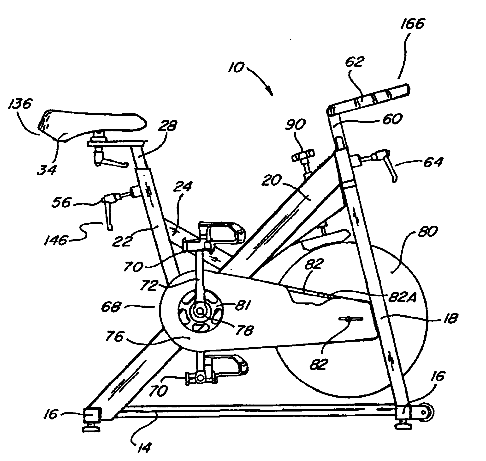
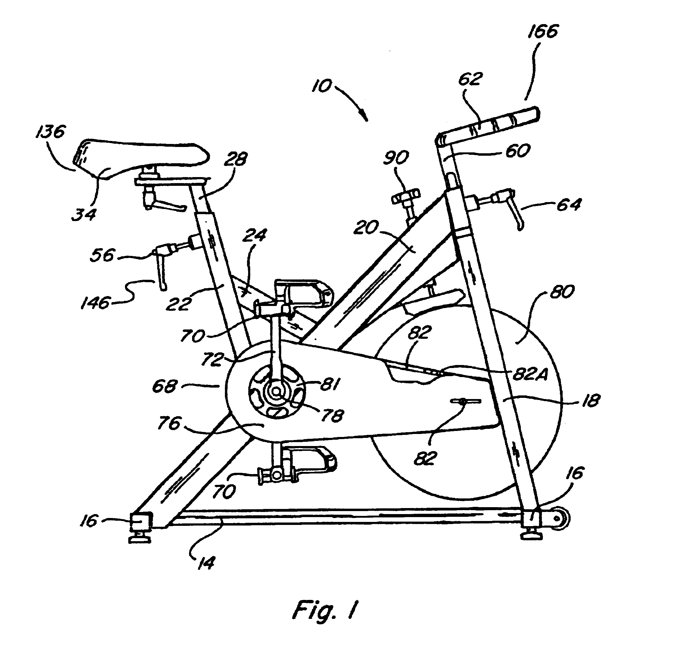
Referring now to FIG. 1, there is shown, in an elevation view, a stationary exercise bicycle 10 in accordance with a preferred embodiment of the present invention. The bicycle 10 has a frame which includes a base section 12 which includes a base longitudinal tube 14 and a pair of base transversal tubes 16. The transversal tubes 16 are rigidly attached to the base longitudinal tube 14, typically, at opposed ends thereof. A front support tube 18 extends upwardly from the base longitudinal tube 14 adjacent the first end thereof. The front support tube 18 is, preferably, angled relative to the base longitudinal tube 14 so as to extend slightly towards the rear portion of the bicycle 10.

A structurally strong main support tube 20 is joined to and extends upwardly from the rearward portion (or end) of the base longitudinal tube 14. The support tube 20 intersects with and is joined to an upper portion of the front support tube 18.

A rear support tube 22 is joined to and extends upwardly from...


PUM


Abstract

The invention is directed to a stationary bicycle which has load-providing components allowing for fine-tuned adjustment of the selected load. The load providing components are made of relatively simple mechanical components so as to increase the reliability, reduce the maintenance and provide a relatively smooth cycling feel. In addition, the invention is directed to a stationary bicycle which is manufactured using specific materials and processes so as to provide for a reliable product having a relatively long life cycle characterized by reliable functioning. Furthermore, the stationary bicycle of the invention comprises a design which allows for ergonomic fine tuning of the relative positioning between the various components thereof so as to provide ergonomic adjustments thereby reducing the risk of injury to the body of the individual and allowing for a more efficient workout.

Description

1. Field of The InventionThe present invention relates to the field of exercise equipment, in general, and to an improved stationary exercise bicycle, in particular.2. Prior ArtRelatively recent trends towards physical fitness awareness have led to an increase in the number of individuals exercising on a regular basis in order to keep physically fit. Several types of exercise equipment are currently in use to provide exercise to persons who wish to keep physically fit without venturing outdoors. One of the most popular of such indoor exercise devices is the stationary exercise bicycle.A number of present day gymnasiums and exercise clubs have some type of stationary exercise bicycle apparatus whereby a person pedals a simulated bicycle as a form of exercise. Early exercise bicycles included apparatus designed to support a conventional bicycle so that the rear wheel thereof can rotate against a frictional load. These types of devices fall into several general categories, the first of...

Claims


Application Information

Patent Timeline
Patent Type & Authority Patents(United States)
IPC IPC(8): A63B22/06A63B21/012A63B22/08A63B21/015
CPCA63B21/015A63B22/0605A63B21/1496A63B21/00069A63B21/00076A63B2225/09A63B2225/30A63B21/4049
Inventor FORCILLO, JOHNNY
Owner MAD DOGG ATHLETICS
Why Eureka
Try Eureka