Flue gas energy transfer system

a flue gas energy transfer and heat recovery technology, applied in the field of energy transfer, can solve the problem of not providing subsidiary heating directly to the boiler for improving boiler performan

Inactive Publication Date: 2004-01-06
ZAYAS CARLOS
View PDF8 Cites 12 Cited by
  • Summary
  • Abstract
  • Description
  • Claims
  • Application Information

AI Technical Summary

Problems solved by technology

The above systems however, do not provide subsidiary heating directly to the boiler for improving boiler performance.

Method used


Image

  • Flue gas energy transfer system
  • Flue gas energy transfer system
  • Flue gas energy transfer system

Examples


Embodiment Construction

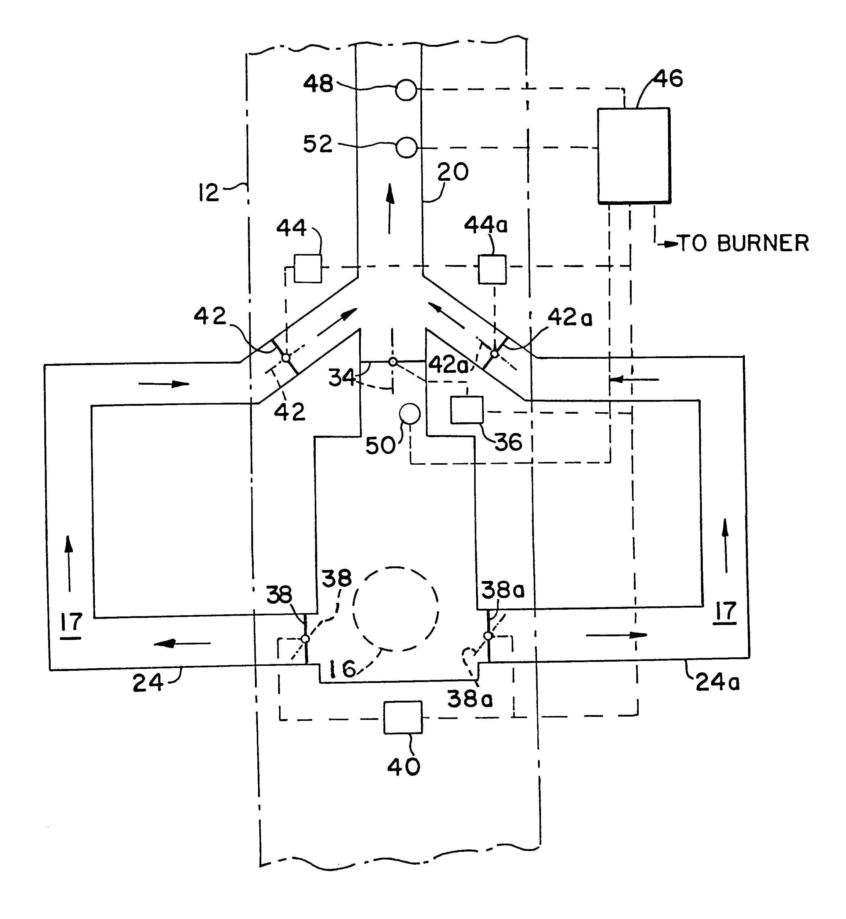
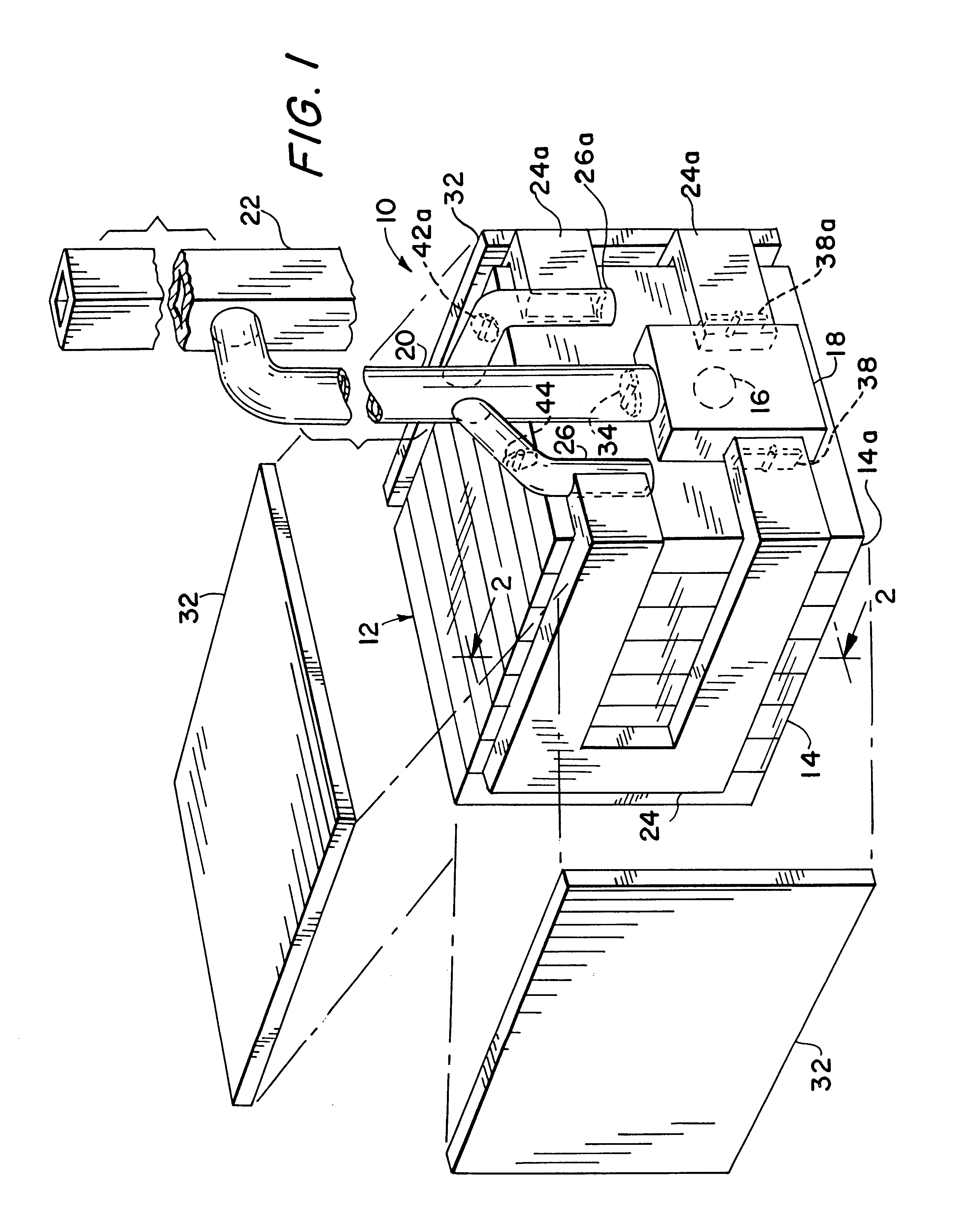
With specific reference now to the figures in detail, it is to be stressed that the particulars shown are by way of example and for the purposes of illustrative discussion of the preferred embodiment of the present invention and is presented in the cause of providing what is believed to be the most useful and readily understood description of the principles and conceptual aspects of the invention. In this regard, no attempt has been made to show structural aspects of the invention in more detail than is necessary for a fundamental understanding of the invention, the description taken with the drawings should make it apparent to those skilled in the art how the invention may be embodied in practice.

Referring now in detail to FIG. 1 of the drawings, there is shown a flue gas energy transfer system 10 in accordance with this invention as applied to a boiler 12. For the purpose of this illustrative description, the boiler 12 is a commercial hot water boiler fired internally by a gas, oi...


PUM


Abstract

A flue gas energy transfer system for increasing the efficiency of hot-water and / or steam boiler. They system utilizes an arrangement of heat transfer ducts with damper elements for the selective diverting exhaust combustion gases. The heat transfer ducts transmit the exhaust gases for contiguous contact with the boiler for conductive heat transfer. The heated gases are retained within the transfer duct after boiler shutdown for maintaining an elevated water temperature.

Description

1. Field of the InventionThis invention relates generally to energy transfer and especially to a heat recovery system for liquid heaters.In particular, the flue gas energy transfer system of this invention concerns a subsidiary heat off-take for boilers.2. Background InformationLiquid boilers used for low-pressure steam and hot water installations typically have a pressure vessel divided interiorly into water filed sections, tubes and / or coils. The liquid is separated from a combustion zone by a heating surface. And an oil or gas fired burner produces radiant energy and combustion gases for heating the liquid. The combustion gases are usually exhausted through a flue and discharged into the atmosphere through a chimney.Various systems have been developed for recuperating heat from exhaust combustion gases. For example, U.S. Pat. No. 6,357,396 describes an apparatus for exchanging heat from the exhaust gas to preheat combustion air. A method for utilizing waste heat for heating room ...

Claims


Application Information

Patent Timeline
Patent Type & Authority Patents(United States)
IPC IPC(8): F22B13/00F24D12/02F24D12/00
CPCF22B13/00F24D12/02F24D2200/18Y02B30/14Y02B30/00
Inventor ZAYAS, CARLOS
Owner ZAYAS CARLOS
Why Eureka
Try Eureka