Re-configurable fibre wireless network

a wireless network and reconfigurable technology, applied in wireless communication, wireless communication, multiplex communication, etc., can solve the problems of reducing the service life of the base station

Inactive Publication Date: 2004-01-06
LUCENT TECH INC
View PDF17 Cites 226 Cited by
  • Summary
  • Abstract
  • Description
  • Claims
  • Application Information

AI Technical Summary

Problems solved by technology

If hot-spots occur in the network, traffic demand may exceed the network capacity available (in the microwave carrier available in that cell, and / or in the network feeding the wireless base station which supports the microwave antenna in that cell), leading to rejection of calls.
However, this fixed configuration is not responsive to changing traffic densities.
One drawback of this arrangement is that it is required to provide wavelength selection means in the optical network unit associated with each base station, which increases complexity, costs, maintenance and space requirements for each base station.

Method used


Image

  • Re-configurable fibre wireless network
  • Re-configurable fibre wireless network
  • Re-configurable fibre wireless network

Examples


Embodiment Construction

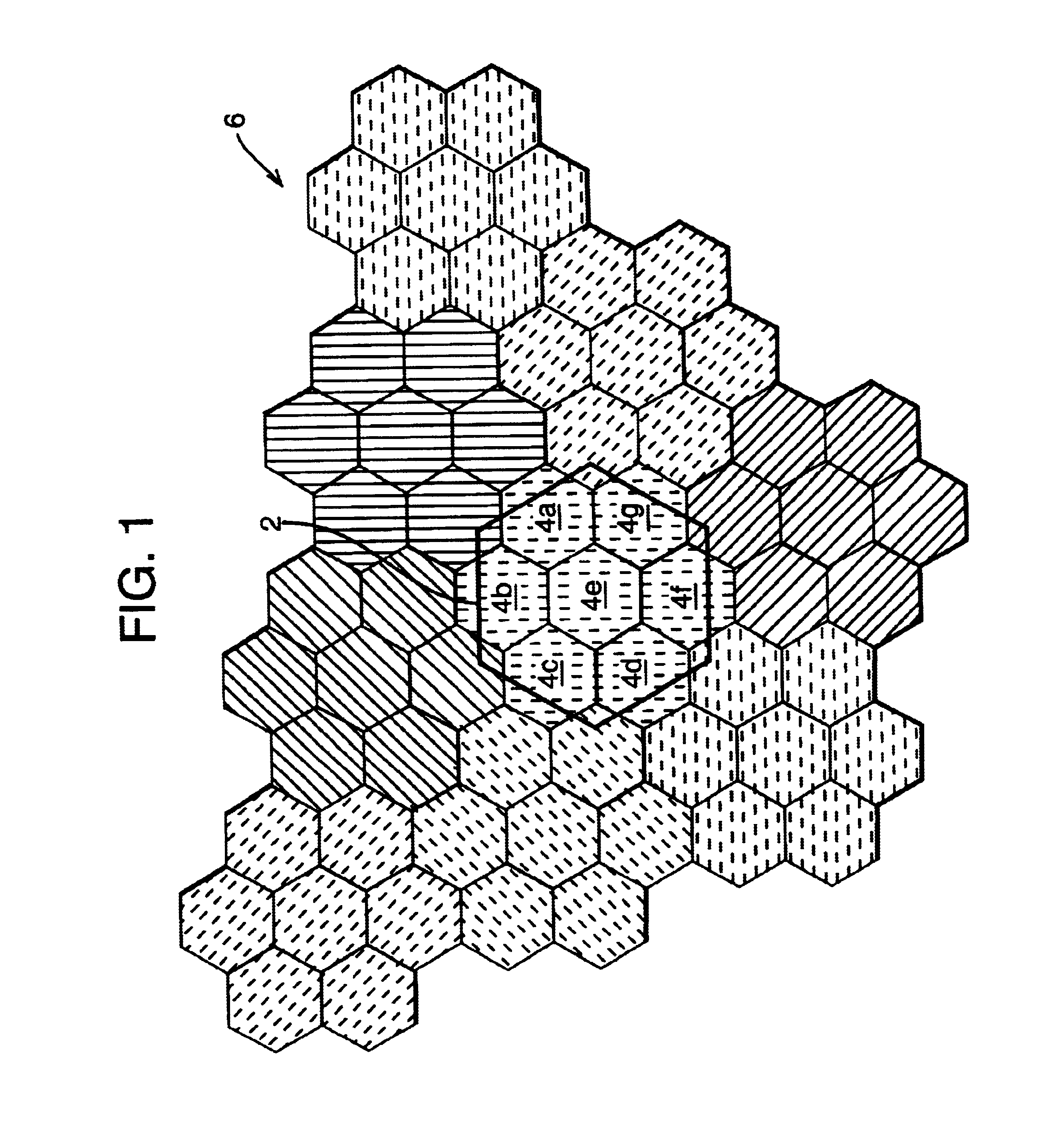
Referring to FIG. 1, there is illustrated a portion 6 of a cellular network. In the portion of the cellular network 6 shown in FIG. 1, the cells are split into micro-cells. For example, the micro-cells 4a to 4g are derived from the macro-cell 2 of a conventional cellular structure. In the portion of the cellular network illustrated in FIG. 1 it is assumed that each micro-cell is provided with an omni-directional antenna. Thus the cellular structure shown in FIG. 1 has evolved from a macro-cellular structure in which each macro-cell had a single omni-directional antenna, to a micro-cellular structure in which each macro-cell is replaced by seven micro-cells each having an omni-directional antenna.

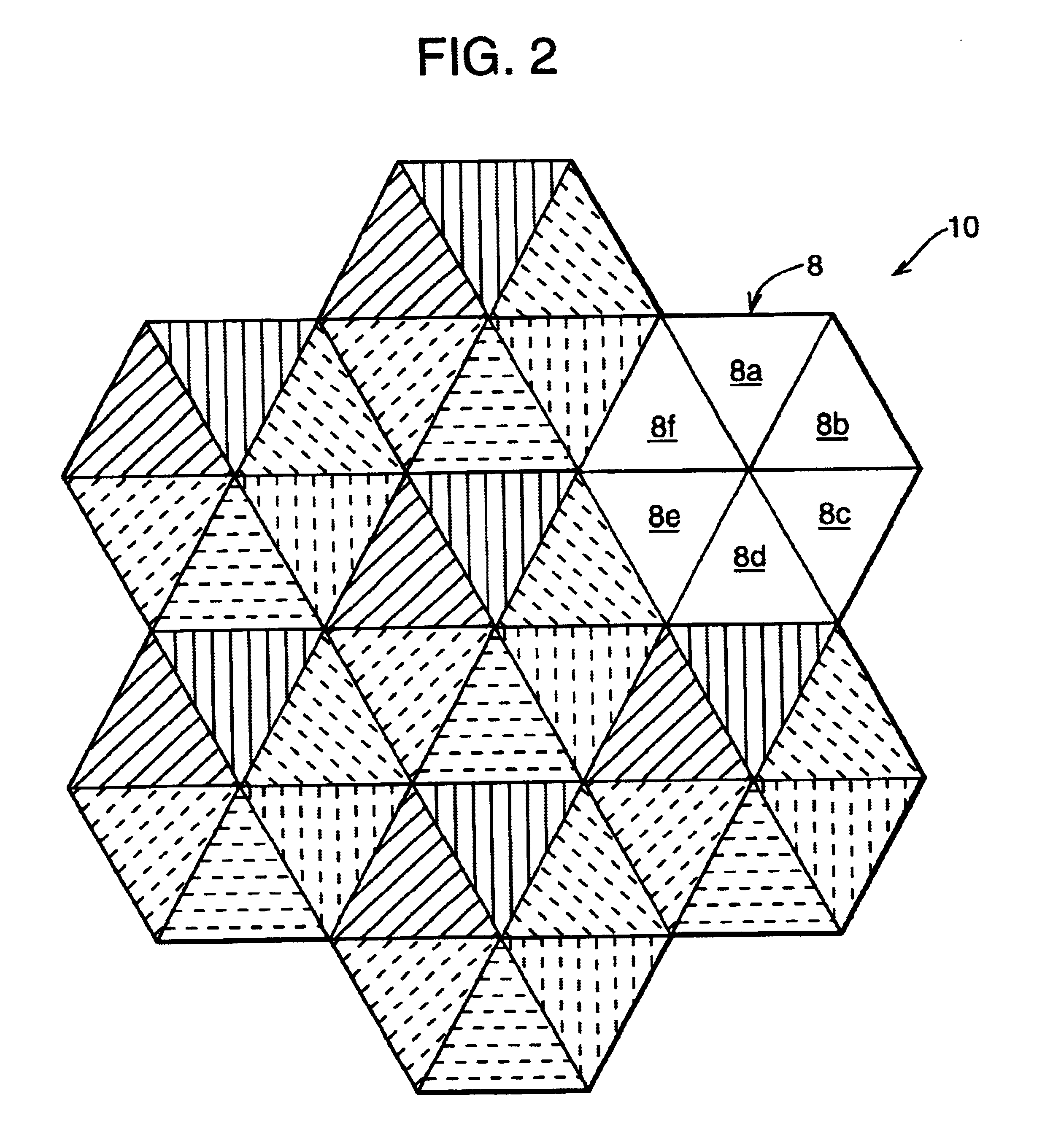
FIG. 2 illustrates schematically the evolution from a macro-cellular structure to a micro-cellular structure using multi-sector antennas. The portion 10 of the cellular network shown in FIG. 2 has each macro-cell split into sectors: by employing a multi-sector antenna in each macro-cell. Thu...


PUM


Abstract

A wireless communication system comprises a base station controller and a base station interface connected to the base station controller by a central optical fiber. The base station interface may include a flexible wavelength router. At least one base station is connected to the base station interface, and the central optical fiber carries at least one communication channel associated with an optical signal having one of a plurality of wavelengths. The base station interface selectively provides a communication path between the base station controller and at least one base station using at least one communication channel.

Description

The present invention relates to a wireless communication network having a reconfigurable infrastructure, and particularly to such a network in which communication channels are provided to distributed base stations via optical fiber cables.BACKGROUND TO THE INVENTIONIn wireless communication systems traffic densities in a particular area are not constant. Wireless networks are usually laid out as a set of cells, which provide coverage of a larger region. At certain times, traffic increases in certain cells, providing so-called `hot-spots`. If hot-spots occur in the network, traffic demand may exceed the network capacity available (in the microwave carrier available in that cell, and / or in the network feeding the wireless base station which supports the microwave antenna in that cell), leading to rejection of calls.Current wireless systems are divided into cells. Each cell uses one or more dedicated carrier frequencies, with each carrier frequency carrying a limited number of voice o...

Claims


Application Information

Patent Timeline
Patent Type & Authority Patents(United States)
IPC IPC(8): H04B10/12H04J14/02H04Q7/30H04Q7/36H04B10/2575H04W88/08
CPCH04B10/25752H04B10/25753H04J14/02H04W88/08H04J14/0298
Inventor KOONEN, ANTONIUS MARCELLUS JOZEF
Owner LUCENT TECH INC
Why Eureka
Try Eureka