
Method and apparatus for performing rotate operations using cascaded multiplexers

a cascaded multiplexer and rotation operation technology, applied in the field of logic circuits for performing arithmetic operations, can solve the problems of non-uniform circuit layout of logarithmic rotators, high circuit drive levels, and inability to perform sub-field rotation operations of typical logarithmic rotate circuits

Inactive Publication Date: 2004-01-06
GOOGLE LLC
View PDF10 Cites 22 Cited by
  • Summary
  • Abstract
  • Description
  • Claims
  • Application Information

AI Technical Summary

Problems solved by technology

Logarithmic rotators exhibit a non-uniformity in circuit layout, as the wires that couple the most-significant bits to the inputs of the multiplexers that select the least-significant bits (for a left rotator) are longer and therefore require higher circuit drive levels (e.g., larger transistors).
Additionally, typical logarithmic rotate circuits cannot be used to perform sub-field rotate operations unless circuitry is added to interconnect ends of the sub-fields.

Method used


Image

  • Method and apparatus for performing rotate operations using cascaded multiplexers
  • Method and apparatus for performing rotate operations using cascaded multiplexers
  • Method and apparatus for performing rotate operations using cascaded multiplexers

Examples


Embodiment Construction

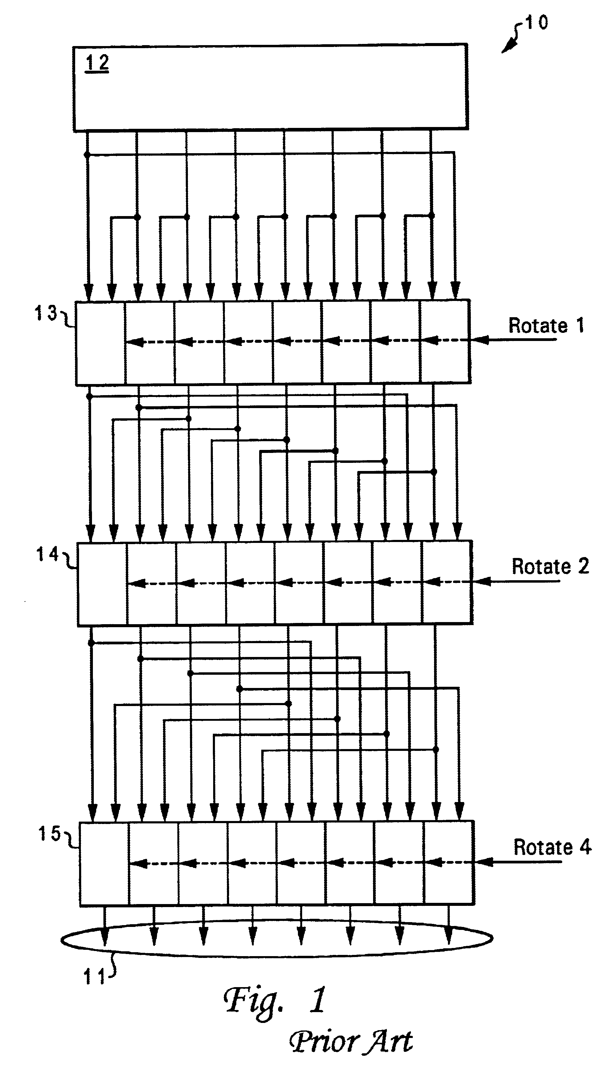
With reference now to the figures, and in particular with reference to FIG. 1, there is depicted a schematic diagram of a prior art logarithmic rotator 10. As shown, input register 12 provides an operand to be rotated according to a rotate amount. The rotate amount is represented in FIG. 1 as three bit lines Rotate n where n is the amount of left rotate associated with each of the rotate bits. The operation of logarithmic rotator 10 is straightforward in that a logic "1" value for Rotate 1 will cause multiplexer 13 to shift the lower seven bits provided by input register 12 to the left, and the most-significant "wraparound" bit will be provided to the least-significant position. This is provided by the connection of multiplexer 13 to input register 12, whereby switches within multiplexer 13 may select the directly corresponding bit from input register 12 or the bit one position to the right. Multiplexers 13, 14, and 15 are drawn so that a logic "1" selector value will enable the rig...


PUM


Abstract

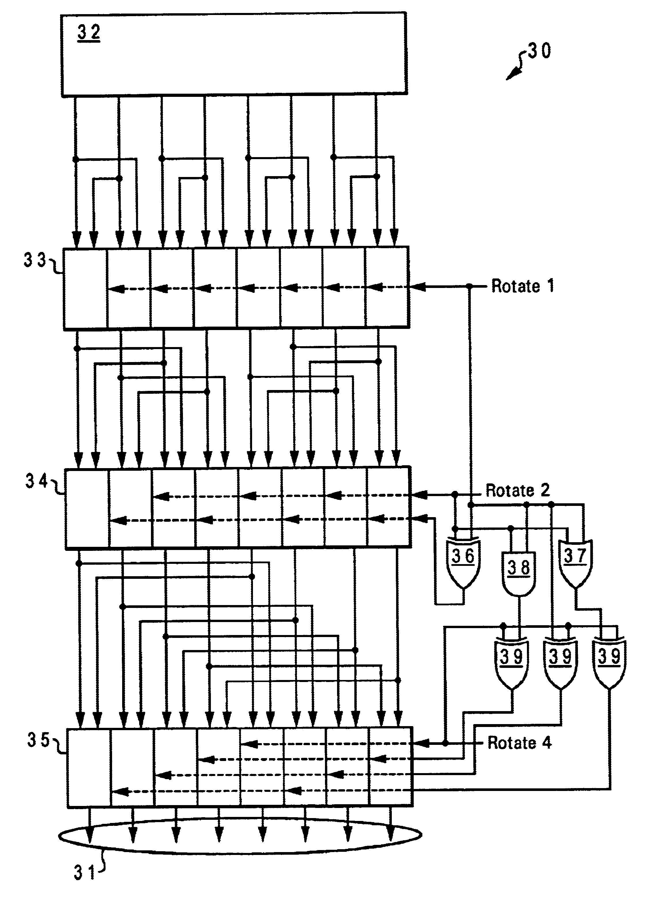
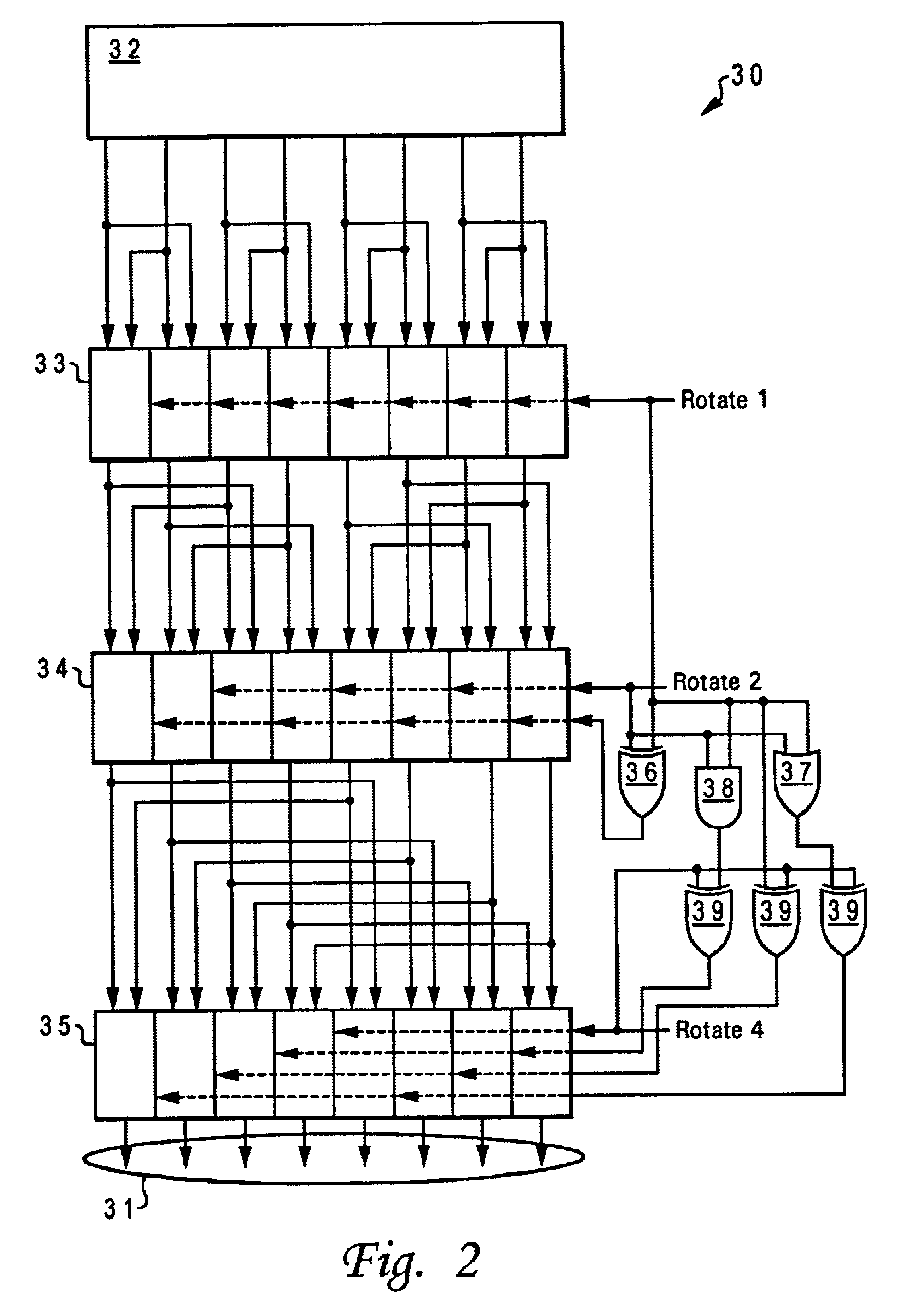
A method and apparatus performing rotate operations using cascaded multiplexers provides a scalable rotator circuit having a sub-field rotate capability that requires no additional interconnects at the sub-field endpoints. The rotator performs bit field swap operations at each stage of a series of cascaded multiplexers. The bit field size increases monotonically from a single bit to half of the rotator operand size. The control logic selects swap operations for each individual bit field at each stage, in order to arrange a desired rotated output vector.

Description

1. Technical FieldThe present invention relates generally to logic circuits for performing arithmetic operations, and more specifically to a method and apparatus for performing rotate operations using cascaded multiplexers.2. Description of the Related ArtRotators are used in the arithmetic logic units (ALUs) of microprocessors and are also used in dedicated logic circuits. Rotate operations in graphics applications are efficiently performed using rotators and rotating operations can also be performed in dedicated processing circuits such as parallel-to-serial converters.High speed rotator circuits using multiplexers are well known in the art. Logarithmic rotators accomplish rotate operations by sequentially performing rotates by fixed powers of 2 in cascaded stages, selecting a rotate or not rotate operation for each stage. By using multiplexers rather than clocked registers, the shift or rotate operations may be performed within a single clock cycle. The time required to complete ...

Claims


Application Information

Patent Timeline
Patent Type & Authority Patents(United States)
IPC IPC(8): G06F7/76G06F5/01
CPCG06F7/762G06F5/015
Inventor HOFSTEE, H. PETERNGO, HUNG C.NOWKA, KEVIN J.SAWADA, JUN
Owner GOOGLE LLC
Learn More