
Method for forming a head wall from an anchor pile and reinforcing member for said anchor pile structure

a technology of anchor pile and anchor pile, which is applied in the direction of bulkhead/pile, soil preservation, artificial islands, etc., can solve the problems of not being able to improve the appearance of the front face giving no opportunities for improving the appearance of the retaining wall, and stackable prefabricated modules not being able to control the forces that a

Inactive Publication Date: 2004-01-13
GOLCHEH JOSEPH
View PDF13 Cites 35 Cited by
  • Summary
  • Abstract
  • Description
  • Claims
  • Application Information

AI Technical Summary

Benefits of technology

Another object of the proposal of the invention is to provide a novel reinforcing element suitable for overcoming the above-mentioned drawbacks while being capable of providing an improved reinforcing function by establishing a higher anchoring force while using an element that is simple, quickly made, and low in cost.
According to a characteristic relating more particularly to the retaining wall, the attachment parts of the reinforcing element are placed in the immediate vicinity of a rib so as to reduce the bending forces applied to the transverse connection bar.

Problems solved by technology

Although such walls are capable of achieving the intended objective, they are heavy and expensive to construct and in practice they are unsuitable for use with heights that are relatively large or in sites that present difficulties for moving heavy and powerful hoisting equipment.
Such a proposal appears to be more practical and less expensive, but it still gives rise to problems when it is necessary to satisfy retention requirements over a great height.
In addition, it can be observed that such proposals give no opportunities for improving the appearance of the front face of the retaining wall, e.g. by including niches for plants.
However, the use of stackable prefabricated modules does not make it possible to control the forces that act on them by means of the mass of material that is to be contained.
Such a technique is not easy to implement and gives rise to a problem of distributing forces amongst the various attachment points between the mesh and the modules.
It has been found that the very use of this technique causes different attachment points to be stressed differently and as a result that are uncontrollable force distributions that lead to zones of the retaining wall being associated with portions of the mesh that are not anchored or that are poorly anchored in the material to be contained.
That solution is found to be unsatisfactory in many respects.
Firstly, making a reinforcing element on that principle is relatively expensive since the element has the same structure over its entire length and because it needs to be anchored over its entire length by means of the materials that are to be contained.
Given this requirement, the cost price of making it is not negligible due to the raw materials used and the cost of fabrication.
This unavoidably gives rise to a risk of breakage under tension because of the relatively small mass presented locally by the prefabricated modules.

Method used


Image

  • Method for forming a head wall from an anchor pile and reinforcing member for said anchor pile structure
  • Method for forming a head wall from an anchor pile and reinforcing member for said anchor pile structure
  • Method for forming a head wall from an anchor pile and reinforcing member for said anchor pile structure

Examples


Embodiment Construction

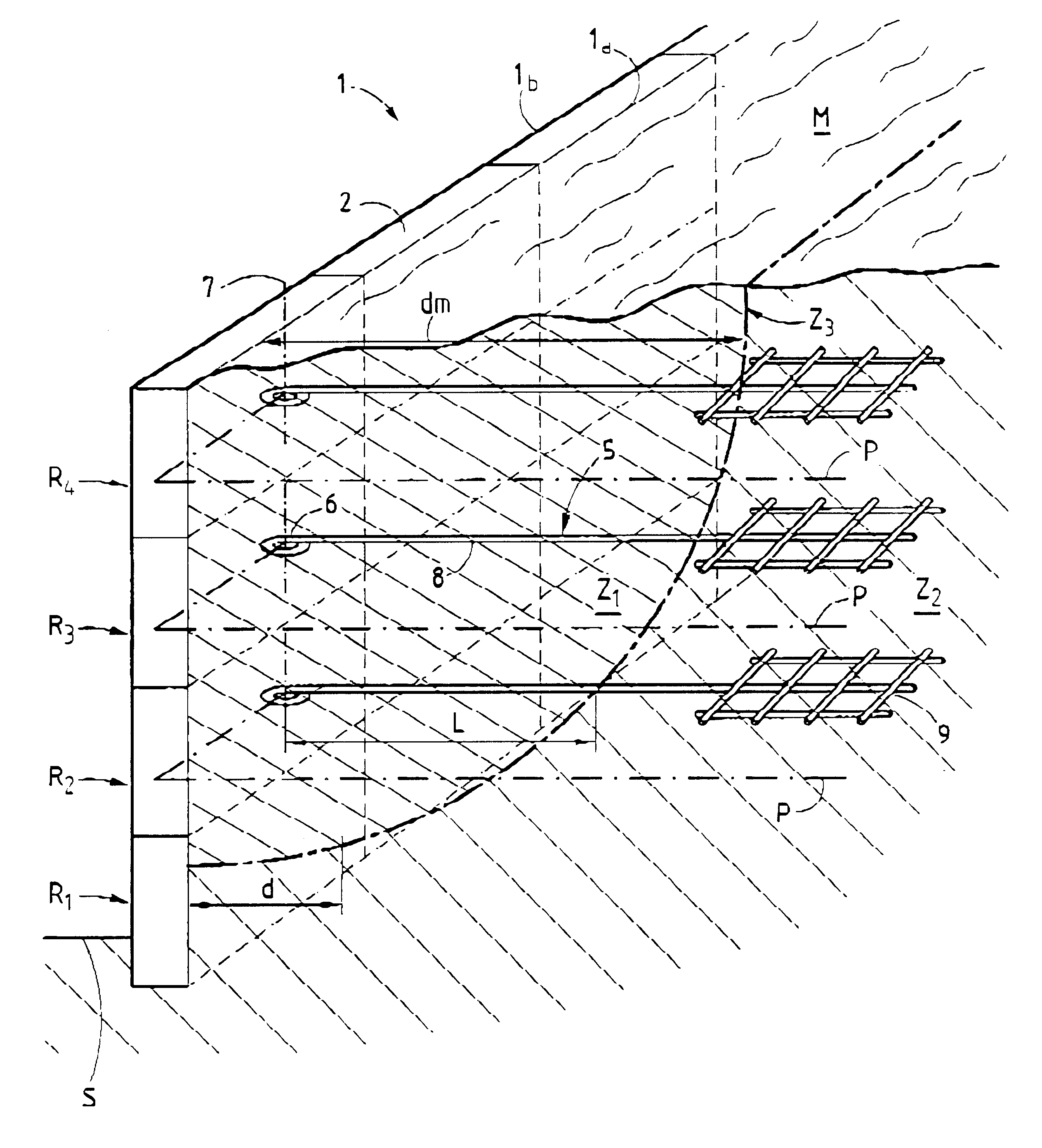
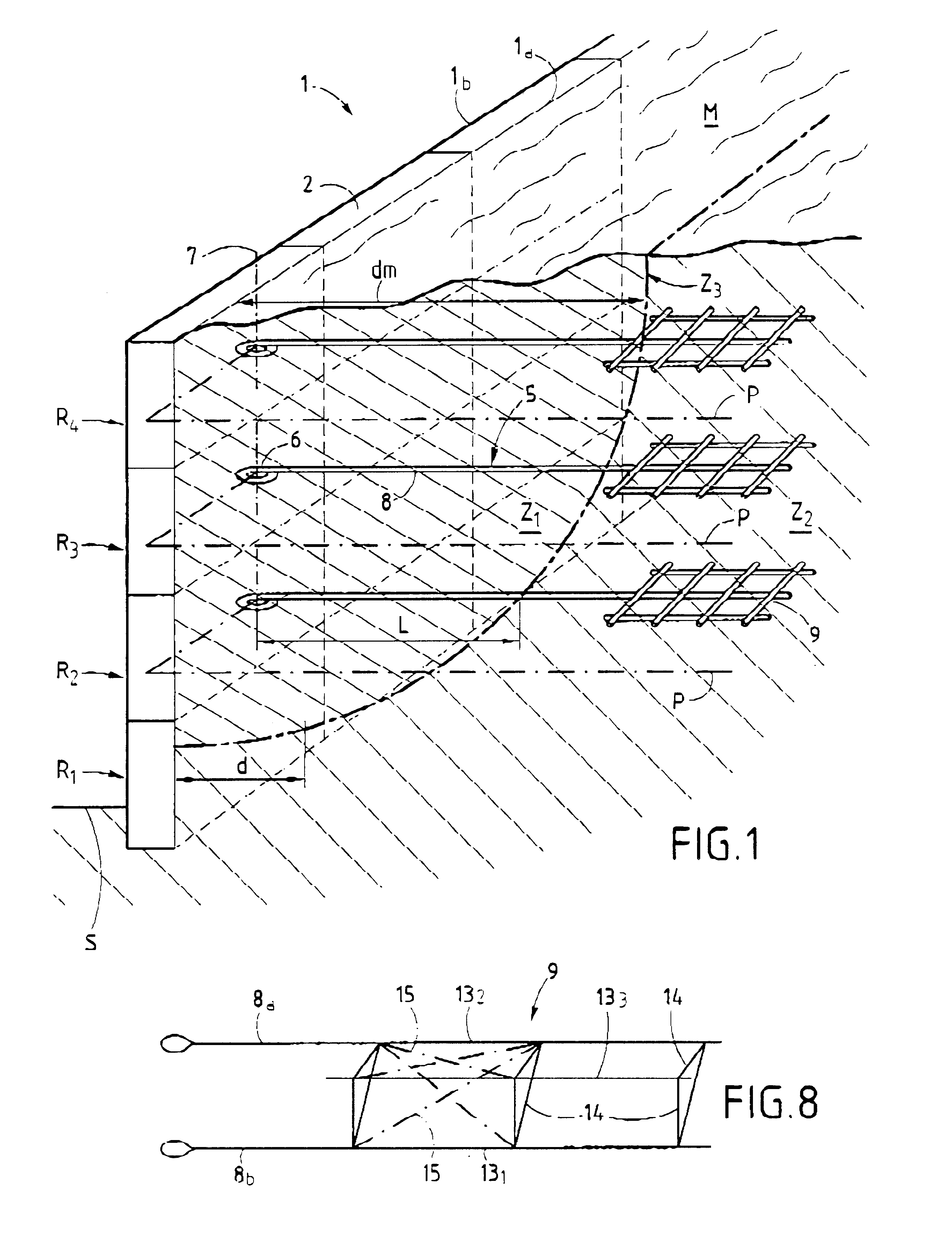
FIG. 1 is a diagrammatic view of a retaining work given overall reference 1 and implemented in the form of a wall that rises directly or indirectly from ground S, the wall being made up by associating facing elements or modules 2, e.g. prefabricated elements or modules, which are juxtaposed in horizontal rows R.sub.1, R.sub.2, R.sub.3, and R.sub.4, for example, being stacked in directly superposed manner as shown in the perspective view, or else being interleaved using a bond such as an offset from one row to the next. It could also be envisaged to superpose the modules so that they are stepped relative to one another, e.g. back towards the mass to be retained.

Such a work which has the appearance of a wall is intended to retain a mass M which is generally constituted by a filling of earth or analogous material delivered as the wall is built up and which is generally not very compacted.

The retaining method of the wall 1 is based on the principle that a mass such as M is found not to ...


PUM


Abstract

The invention relates to the field of building and is applicable to retaining walls. The reinforcing element is characterized in that it consists in connecting the back face of the facing to the strong zone by means of a plurality of reinforcing elements (5) disposed substantially horizontally in superposed planes, and in selecting said elements in such a manner that each of them comprises an anchoring portion that is included in the strong zone and that is constituted by a mesh comprising more than two longitudinal bars, of which only some extend as far as the facing to define a portion that works in traction, which portion has an attachment part for connection to the facing at its end remote from the anchoring portion.

Description

The present invention relates to the field of supporting or retaining natural or artificial masses of more or less movable material that, due to erosion, vibration, cracking, or cleavage, is liable to suffer from landslides that are harmful to themselves and / or to the surroundings.Although numerous implementations can be envisaged, a preferred application of the invention lies in retaining the front faces of earthworks that are cut or filled relative to a site to be protected, in particular roadways or railway lines, without this list being exhaustive.PRIOR ARTTo solve the above problem, various technical proposals have been made based on the idea that it is appropriate to raise a screen in the form of a wall that performs the function of retaining a mass of material behind an upstream, back, or "wrong" face.It is rapidly apparent that such screens need to withstand horizontal stresses coming from the retained earth.To satisfy that requirement, one prior technical proposal is to mak...

Claims


Application Information

Patent Timeline
IPC IPC(8): E02D29/02
CPCE02D29/0216E02D29/0241E02D29/025
Inventor GOLCHEH, JOSEPH
Owner GOLCHEH JOSEPH
Learn More