Light guide plate, surface light source device and display

a surface light source and light guide plate technology, applied in the direction of lighting and heating apparatus, instruments, machines/engines, etc., can solve the problems of inability to direct an emission, inefficient illumination, and difficulty in providing an object to be illuminated, so as to improve the display

Inactive Publication Date: 2004-01-13
ENPLAS CORP
View PDF6 Cites 55 Cited by
  • Summary
  • Abstract
  • Description
  • Claims
  • Application Information

AI Technical Summary

Benefits of technology

An object of the present invention is to provide a light guide plate improved as to satisfy the above-mentioned demand, a surface light source device improved by making use of the light guide plate and a display improved by making use of the surface light source device.
Such a construction is suitable for a light guide plate having an incidence face supplied with light from a plurality of point-like light emitters. That is, if a plurality of point-like light emitters are combined with the light guide plate, no great difference arises among light supply paths of the respective point-like light emitters because the incidence face is located at a corner portion. This contrasts apparently with the arrangement shown in FIG. 15. In the case of the arrangement shown in FIG. 15, the incidence faces located at two locations distant from each other cause the corresponding LEDs to produce light paths which are greatly different from each other. The present invention is able to avoids such a situation.
A display in accordance with the present invention is obtained by disposing the surface light source device improved as above for illuminating a liquid crystal display panel. The display inherits the above advantage of the surface light source device. That is, the liquid crystal display panel is illuminated effectively from a desired direction, providing a clear display screen.

Problems solved by technology

But some problems arise as follows.
This makes it difficult to supply an object to be illuminated, such as liquid crystal display panel, with light from a generally vertical direction.
(3) An point-like light emitter employed, the light emitter brings a divergent property in addition to so-called "oblique emission directionality" as above (2), resulting in an inefficient illumination.
However, such a technique relying on a light scattering pattern is not capable of directing an emission positively to a desired direction (usually, a roughly frontal direction), although it is able to weaken the directionality through a light scattering effect.
Although other prior arts include a method, according to which an emission face or back face is roughened overall, and another method, according to which a light diffusion sheet is arranged additionally along an emission face, such methods are also hardly expected to be capable of directing an emission positively to a desired direction (usually, a roughly frontal direction) because they depend on causing propagation directions of emission to be diversified in order to overcome the problems.
Although a well known prism sheet has a function of directing an emission positively to a desired direction, such an additional sheet, if employed and disposed, will lead to an increased number of components and accordingly to an increased manufacturing cost.
Beside, if applied, in particular, to a small size appliance such as portable phone, it brings a disadvantage because a total thickness of the appliance will be increased.
An arrangement as shown in FIG. 15 suffers from a problem that an projection array determined as to be optimum for one LED is far from being optimum for the other LED because a plurality of LEDs are disposed along a side away from each other.
In other words, it is hardly possible to determine an projection array as to be optimum for every LED for direction-converting light emitted from every LED effectively to a desired direction effectively.
Another problem, which can arise in some cases, is that projections fitting for one LED can disturb an inside propagation or direction conversion of light emitted from the other LED.

Method used


Image

  • Light guide plate, surface light source device and display
  • Light guide plate, surface light source device and display
  • Light guide plate, surface light source device and display

Examples


first embodiment

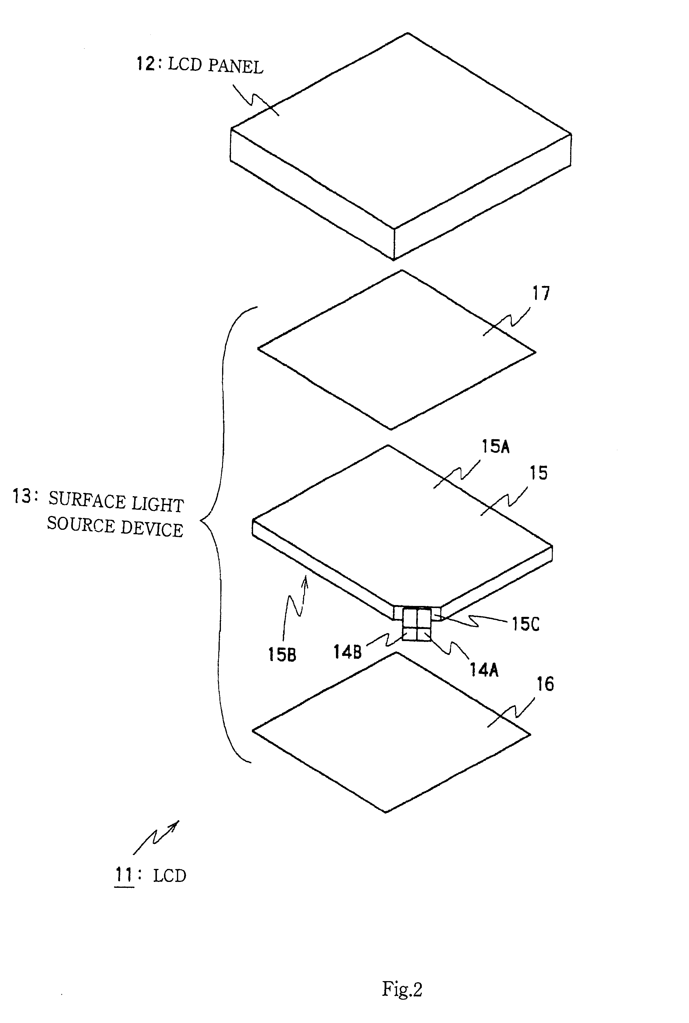
Referring to FIG. 2 in the first place, an outlined structure of a liquid crystal display (liquid crystal display) 11 of this embodiment is illustrated. Liquid crystal display 11 is incorporated, for example, in a portable phone and includes a surface light source device 13 for backlighting panel 12.

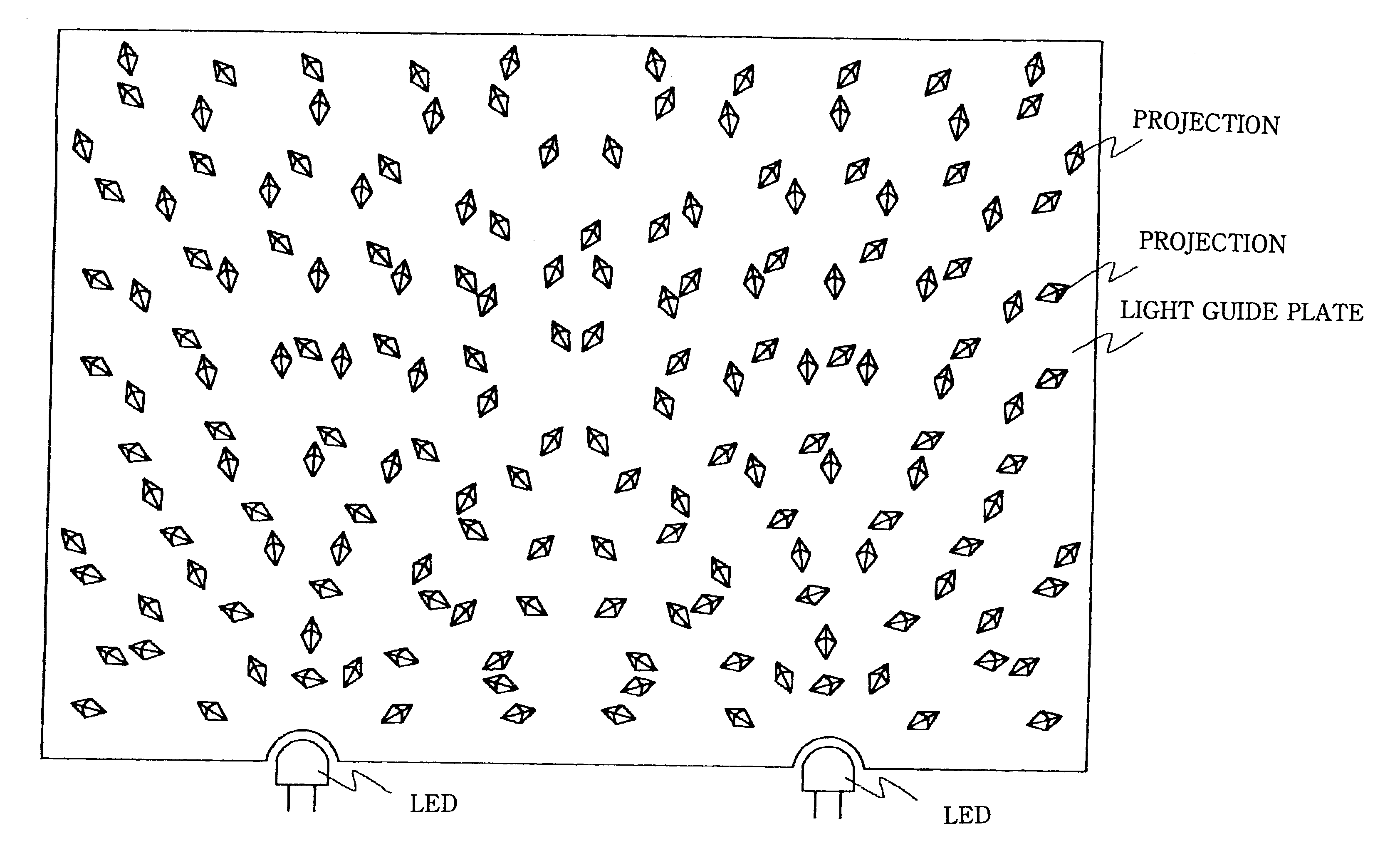
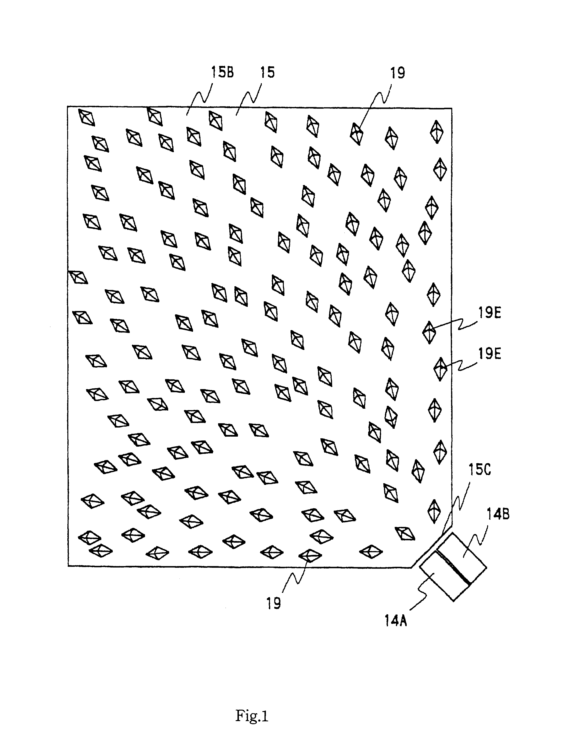
The surface light source device 13 comprises a light guide plate 15, LEDs (point-like light emitters) 14A and 14B, reflection sheet 16 and light diffusion sheet 17. The light guide plate 15 is a light permeable member formed of an acrylic resin (such as PMMA resin) or cycloolefinic resin, being provided with a generally uniform thickness. A major face of the light guide plate 15 provides an emission face 15A and the major face provides a back face 15B.

The light guide plate 15 has a generally rectangular shape at a corner portion of which an incidence face 15C is located. The incidence face 15C is provided by cutting-off at 45 degrees with respect to two sides meeting at the corner portio...

second embodiment

Referring to FIG. 10, shown is a plan view illustrating a part around an incidence face of a light guide plate employed in a surface light source device which is applied to a liquid crystal display of the second embodiment in accordance with the present invention. It is noted that there is no difference between this embodiment and the first embodiment except the instantly employed light guide plate and LED arrangement.

As depicted, the employed light guide plate has a corner portion at which an incidence face is formed as to be composed of two sections. The sections have face-directions inclined toward plus and minus, respectively, with respect to the face-direction of the incidence face 15A which is employed in the first embodiment.

And one LED is disposed at each of the sections correspondingly. According to the above difference in face-direction, one of the directions (of light emitting) of the LEDs is determined so that projections of the ridges are inclined toward the plus side b...

third embodiment

Referring to FIGS. 11A and 11B, shown are a plan view and cross section view respectively illustrating a part around an incidence face of a light guide plate employed in a surface light source device which is applied to a liquid crystal display of the third embodiment in accordance with the present invention. It is noted that there is no difference between this embodiment and the first embodiment except the instantly employed light guide plate and LED arrangement.

The instantly employed light guide plate has a corner portion having an obliquely cut-off configuration. That is, the corner portion includes a slope which is inclined with respect to an emission face and back face. An top edge of the slope meets the back face. Accordingly, the back face is larger than the emission face by an area corresponding to an objective area of the slope onto the back face. And, an incidence face is set in this objective area. A plurality of LEDs are disposed as to supply light to the incidence face....


PUM

PropertyMeasurementUnit
distanceaaaaaaaaaa
critical angleaaaaaaaaaa
thicknessaaaaaaaaaa

Abstract

A display has a liquid crystal display panel illuminated by a surface light source device. The surface light source device comprises a primary light source provided with a plurality of point-like light emitters and a light guide plate which is supplied with light by the primary light, the light being introduced in the light guide plate through an incidence face and being emitted through an emission face. The incidence face is located at a corner portion of the light guide plate. A great number of projections for light-advancing-direction-conversion are formed on a back face. Each of the projections includes a pair of slopes formed so as to provide a ridge approaching the back face with an increasing distance from the incidence face. The pairs of slopes form valleys in the light guide plate, the valleys being orientated to be opened toward the corner portion corresponding to the incidence face. Each projection is shaped like, for instance, a quadrangle pyramid. A radial light propagation within the light guide plate starts from the corner portion and gives light which enters the valleys provided by the projections and is subject to direction-conversion toward the emission face. Emission is supplied to the liquid crystal display panel.

Description

1. Field of InventionThe present invention relates to a light guide plate, a surface light source device and a display, in particular, a light guide plate having a corner portion from which light is inputted, a surface light source device employing the light guide plate and a display having a liquid crystal display panel illuminated by the surface light source device. The invention is applied, for example, to a liquid crystal display incorporated in a portable phone, and to a surface light source device and light guide plate employed in the display.2. Related ArtsIt is well known to employ a surface light source device to illuminate a liquid crystal display panel in a liquid crystal display. In general, a surface light source device comprises a light guide plate and a primary light source to supply primary light to the plate. Although rod-like fluorescent lamps (cold cathode tubes) have been broadly adopted as primary light sources, a recent tendency is that alternative ones using a...

Claims


Application Information

Patent Timeline
Patent Type & Authority Patents(United States)
IPC IPC(8): F21V8/00G02B5/02G02B6/00G02F1/1335G02F1/13357
CPCG02B6/0036G02B6/0061G02B6/0018G02B6/0068G02F1/1335
Inventor OHKAWA, SHINGO
Owner ENPLAS CORP
Why Eureka
Try Eureka