Centrifugal chiller with high voltage unit-mounted starters

a centrifugal chiller and starter technology, which is applied in refrigeration machines, lighting and heating apparatus, refrigeration safety arrangements, etc., can solve the problems of shock to the motor, compressor, contactors that switch power, and place a significant load on the electrical supply system of a facility, and add cost and time to the initial installation of the chiller

Inactive Publication Date: 2004-01-20
TRANE INT INC
View PDF3 Cites 32 Cited by
  • Summary
  • Abstract
  • Description
  • Claims
  • Application Information

AI Technical Summary

Problems solved by technology

However, suddenly applying or removing a full 2,000+ volts across the motor leads can place a significant load on a facility's electrical supply system and can be quite a shock to the motor, compressor, and the contactors that switch the power on and off.
Installing a higher voltage chiller separate from its full-voltage and reduced-voltage starters adds cost and time to the initial installation of the chiller because of the extra electrical work that is required in the field to install the two starters.
Larger chillers generally have larger starters, yet they have less room for them because of shipping rules that limit a chiller's ov

Method used


Image

  • Centrifugal chiller with high voltage unit-mounted starters
  • Centrifugal chiller with high voltage unit-mounted starters
  • Centrifugal chiller with high voltage unit-mounted starters

Examples


Embodiment Construction

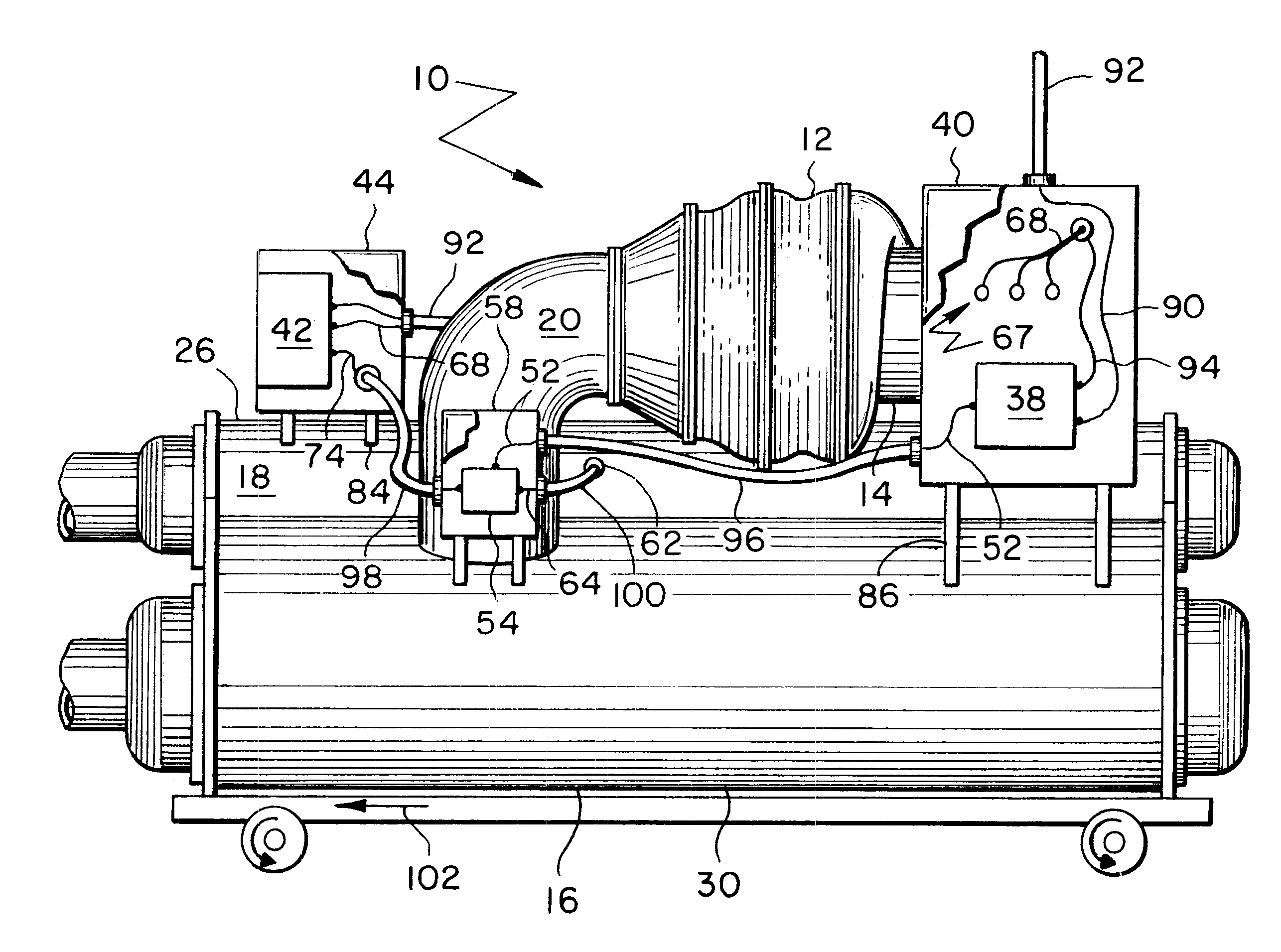
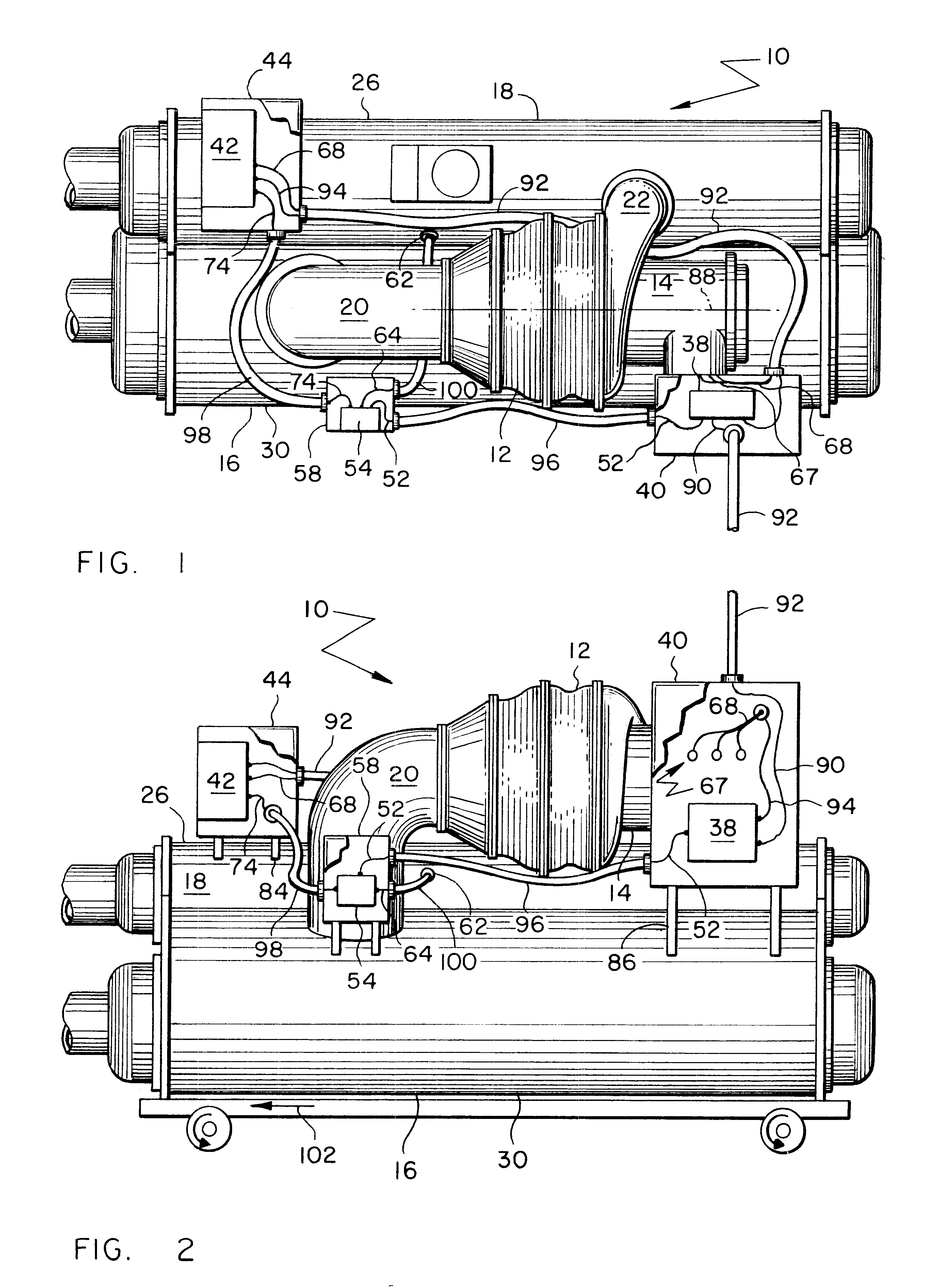
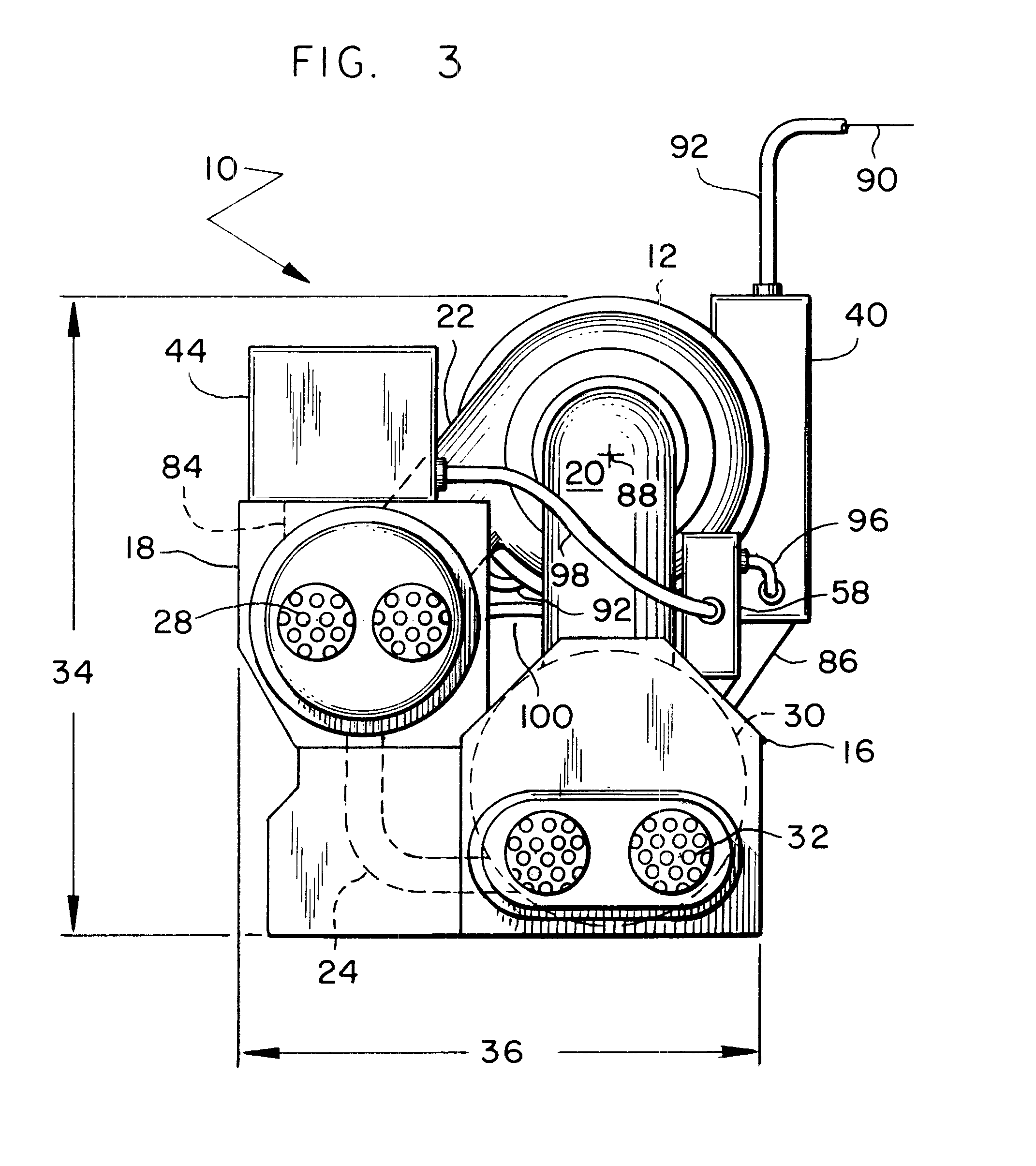
FIGS. 1, 2 and 3 respectively show a top, front and left end view of a centrifugal chiller 10. Basic components of chiller 10 include a centrifugal compressor 12, an alternating current motor 14 driving the compressor, an evaporator 16, and a condenser 18. Compressor 12, condenser 18 and evaporator 16 are connected in fluid communication with each other to create a conventional closed-loop refrigerant circuit for providing chilled water.

In basic operation, a suction elbow 20 conveys relatively cool, low-pressure refrigerant gas from evaporator 16 to a suction side of compressor 12. Compressor 12 compresses the refrigerant and discharges it, at a higher pressure and temperature, through a discharge volute 22. Volute 22 delivers the refrigerant to condenser 18, which then condenses the refrigerant. A pipe 24 (and / or an economizer) with a flow restriction conveys the condensed refrigerant from condenser 18 to evaporator 16. As the refrigerant passes through the restriction in pipe 24, ...


PUM


Abstract

A centrifugal chiller includes both a unit-mounted full-voltage starter and a unit-mounted reduced-voltage starter. The chiller is rather large with a rated cooling capacity of at least 300 tons and is driven by a motor that is powered by at least 2,000 volts. The chiller includes an evaporator shell and a condenser shell in a staggered arrangement to provide a combined height of between 6 and 12 feet and a combined width of between 5 and 8.5 feet. The staggered arrangement of the shells plus mounting the two starters at opposite sides of the motor provide a chiller whose outer dimensions permit the chiller to be shipped as a single package without exceeding certain shipping limits.

Description

1. Field of the InventionThe subject invention generally pertains to refrigerant systems and more specifically to unit-mounted starters for centrifugal chillers.2. Description of Related ArtTypical centrifugal chillers are refrigerant systems that includes a centrifugal compressor driven by an electric motor. The cooling capacity of the chiller may range from a few tons to a thousand tons or more. The smaller units often operate at 480 volts or less and can be turned on and off by a full-voltage starter, which selectively applies or removes the full supply voltage to the motor.Larger chillers that can provide at least 300 tons of cooling are often powered by higher voltages of 2,000 volts or more. The higher voltage means less current is needed for a given size motor, and less current means lighter gauge power supply lines and / or less power losses in the wires. However, suddenly applying or removing a full 2,000+ volts across the motor leads can place a significant load on a facilit...

Claims


Application Information

Patent Timeline
IPC IPC(8): F25B49/02H02P1/26H02P1/28
CPCF25B49/025H02P1/28F25B2400/077F25B2500/01F25B2500/26F25B2700/195
Inventor DUGA, JOEL S.KOMPERUD, JOHN A.HEIDEN, RICHARD M.
Owner TRANE INT INC
Why Eureka
Try Eureka