Condenser, and centrifugal chiller equipped with the same

a centrifugal chiller and condenser technology, which is applied in the direction of refrigeration components, indirect heat exchangers, lighting and heating apparatus, etc., can solve the problems of deterioration in condensation efficiency and impair performance as a cold instrument, and achieve the effect of suppressing deterioration in condensation efficiency and effective air bleeding

Inactive Publication Date: 2019-02-07
MITSUBISHI HEAVY IND THERMAL SYST
View PDF7 Cites 4 Cited by
  • Summary
  • Abstract
  • Description
  • Claims
  • Application Information

AI Technical Summary

Benefits of technology

[0022]As described above, according to the condenser of the present invention and the centrifugal chiller provided with the same, in the centrifugal chiller using a low pressure refrigerant used at the maximum pressure of less than 0.2 MPaG, it

Problems solved by technology

However, due to the characteristics of the low pressure refrigerants, when a suction force of the turbo compressor acts, there are cases where a part of the inside of a refrigerant passage may be under a negative press

Method used


Image

  • Condenser, and centrifugal chiller equipped with the same
  • Condenser, and centrifugal chiller equipped with the same

Examples


Embodiment Construction

[0025]Hereinafter, embodiments of the present invention will be described with reference to the drawings.

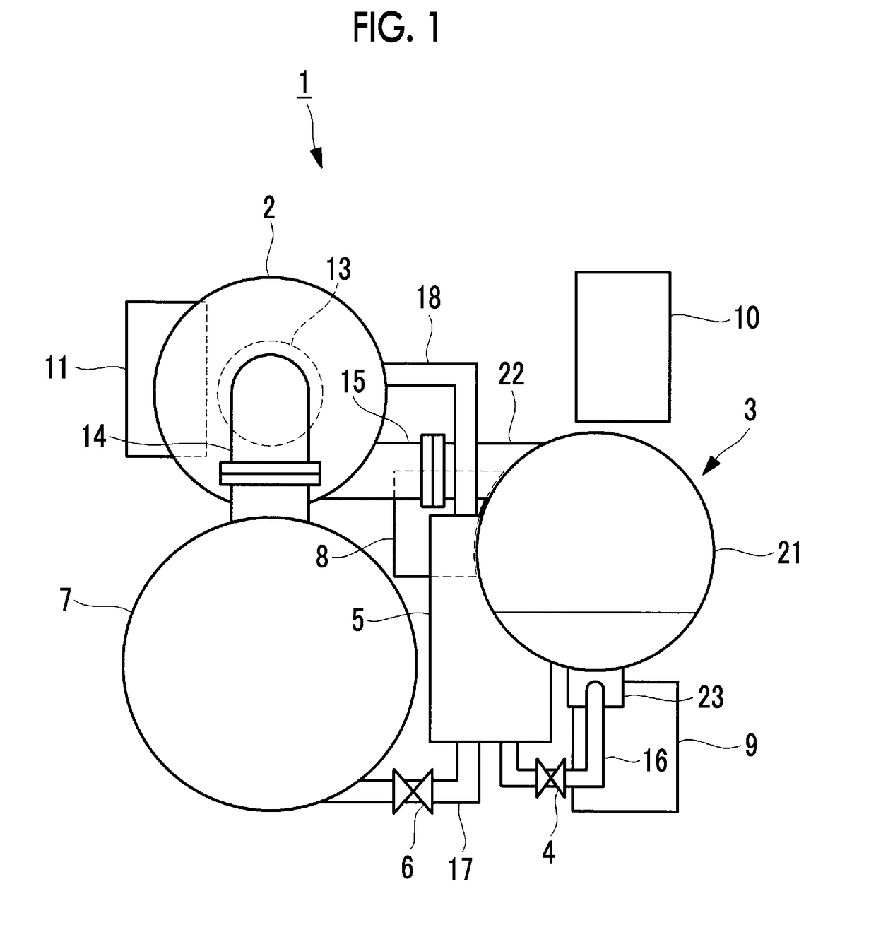
[0026]FIG. 1 is a general view of a centrifugal chiller according to an embodiment of the present invention. A centrifugal chiller 1 is configured in a unit state including a turbo compressor 2 that compresses a refrigerant, a condenser 3, a high-pressure expansion valve 4, an economizer 5, a low-pressure expansion valve 6, an evaporator 7, a lubricant tank 8, a circuit box 9, an inverter unit 10, an operation panel 11, and the like. The lubricant tank 8 is a tank storing lubricant supplied to bearings, a speed increaser, and the like of the turbo compressor 2.

[0027]The condenser 3 and the evaporator 7 are formed in cylindrical shell shapes having high pressure resistance and are disposed so as to be parallel and adjacent to each other in a state where their axis lines extend in a substantially horizontal direction. The condenser 3 is disposed at a position relatively higher than...


PUM


Abstract

The present invention makes it possible in a centrifugal chiller utilizing a low pressure refrigerant used at a maximum pressure of less than 0.2 MPaG to effectively extract, in high concentration, non-condensible gas that has mixed into the low pressure refrigerant, and thus suppresses reductions in condensing efficiency. This condenser (3) is equipped with: a shell vessel (21) into which a low pressure refrigerant used at a maximum pressure of less than 0.2 MPaG is introduced; a refrigerant inlet (22) which is provided to the top portion of the shell vessel (21); a refrigerant outlet (23) which is provided to the bottom portion of the shell vessel (21); a heat transfer tube bundle (25) in which a plurality of heat transfer tubes (25a) circulating a chilled liquid in the interior thereof are bundled, and which extends along the interior of the shell vessel (21); a gas extraction tube (31) in the heat transfer tube bundle interior, the gas extraction tube being disposed in the center region in the radial direction of the heat transfer tube bundle (25), forming a tubular shape arranged parallel to the axial direction of the heat transfer tube bundle (25), and having formed in the bottom surface thereof non-condensible gas extraction holes (31a) for extracting non-condensible gas that has mixed into the low pressure refrigerant; and a gas extraction device (33) which is connected to the gas extraction tube (31) in the heat transfer tube bundle interior and extracts the non-condensible gas.

Description

TECHNICAL FIELD[0001]The present invention relates to a condenser gasifying a low pressure refrigerant, and a centrifugal chiller provided with the same.BACKGROUND ART[0002]For example, as a centrifugal chiller used as a heat source for district cooling and heating, a centrifugal chiller configured to include a turbo compressor that compresses a refrigerant, a condenser that condenses the compressed refrigerant, an expansion valve that expands the condensed refrigerant, and an evaporator that evaporates the expanded refrigerant is known.[0003]Generally, a condenser includes a shell container having a cylindrical shell shape extending in a horizontal direction, and a heat transfer pipe bundle is installed so as to penetrate the shell container in a longitudinal direction. The heat transfer pipe bundle is constituted of a number of heat transfer pipes which are bundled at narrow intervals and cause a cooling liquid such as water to circulate therein. The heat transfer pipe bundle is l...

Claims


Application Information

Patent Timeline
IPC IPC(8): F25B1/053F25B39/04F25B43/04F28D7/16F25B49/02
CPCF25B1/053F25B39/04F25B43/04F28D7/1669F25B49/027F25B2339/041F25B2400/13F28B1/02F28B9/10F28D7/163F25B2339/046F25B2339/047
Inventor MIYOSHI, NAOYAWAJIMA, KAZUKI
Owner MITSUBISHI HEAVY IND THERMAL SYST
Why Eureka
Try Eureka