Non-lethal electromagnetic active body

a non-lethal, electromagnetic active body technology, applied in the direction of electric fuzes, ammunition fuzes, instruments, etc., can solve the problems of high frequency disturbance, extremely limited power, and high frequency disturban

Inactive Publication Date: 2004-01-20
DIEHL BGT DEFENCE GMBH & CO KG
View PDF12 Cites 41 Cited by
  • Summary
  • Abstract
  • Description
  • Claims
  • Application Information

AI Technical Summary

Benefits of technology

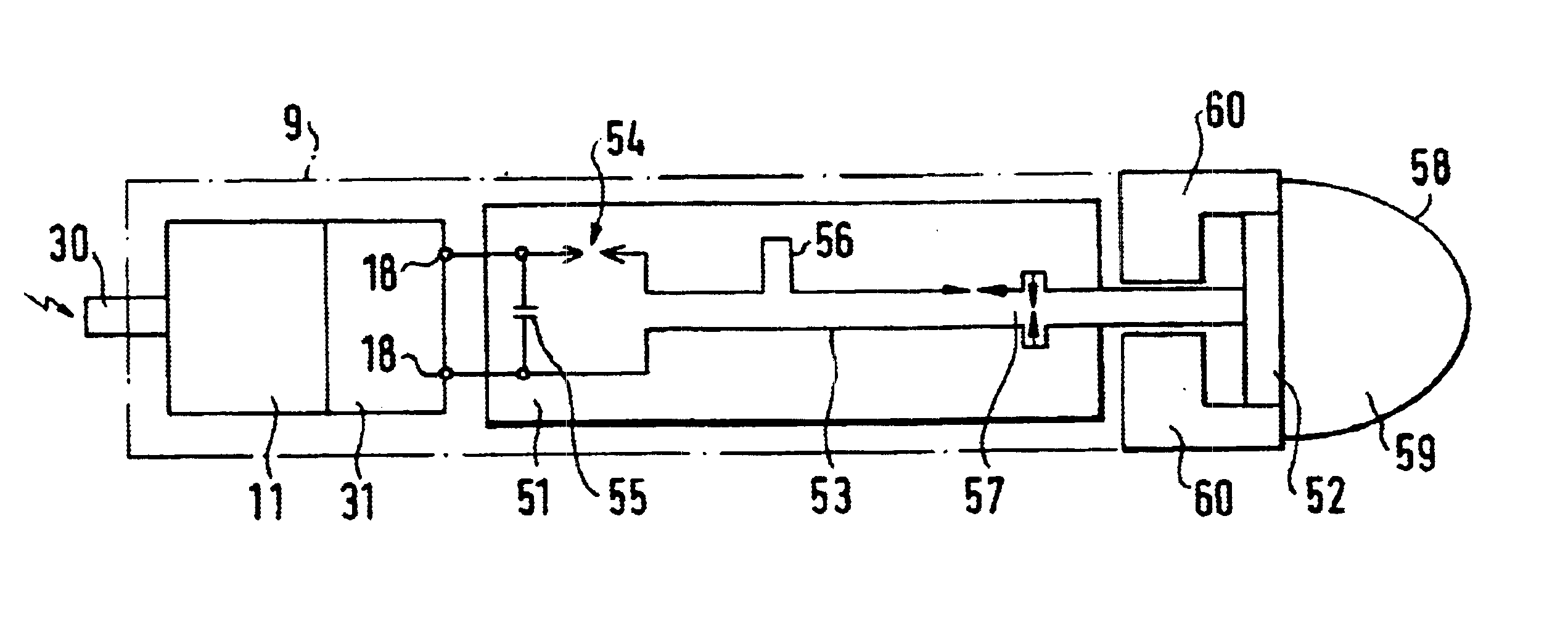
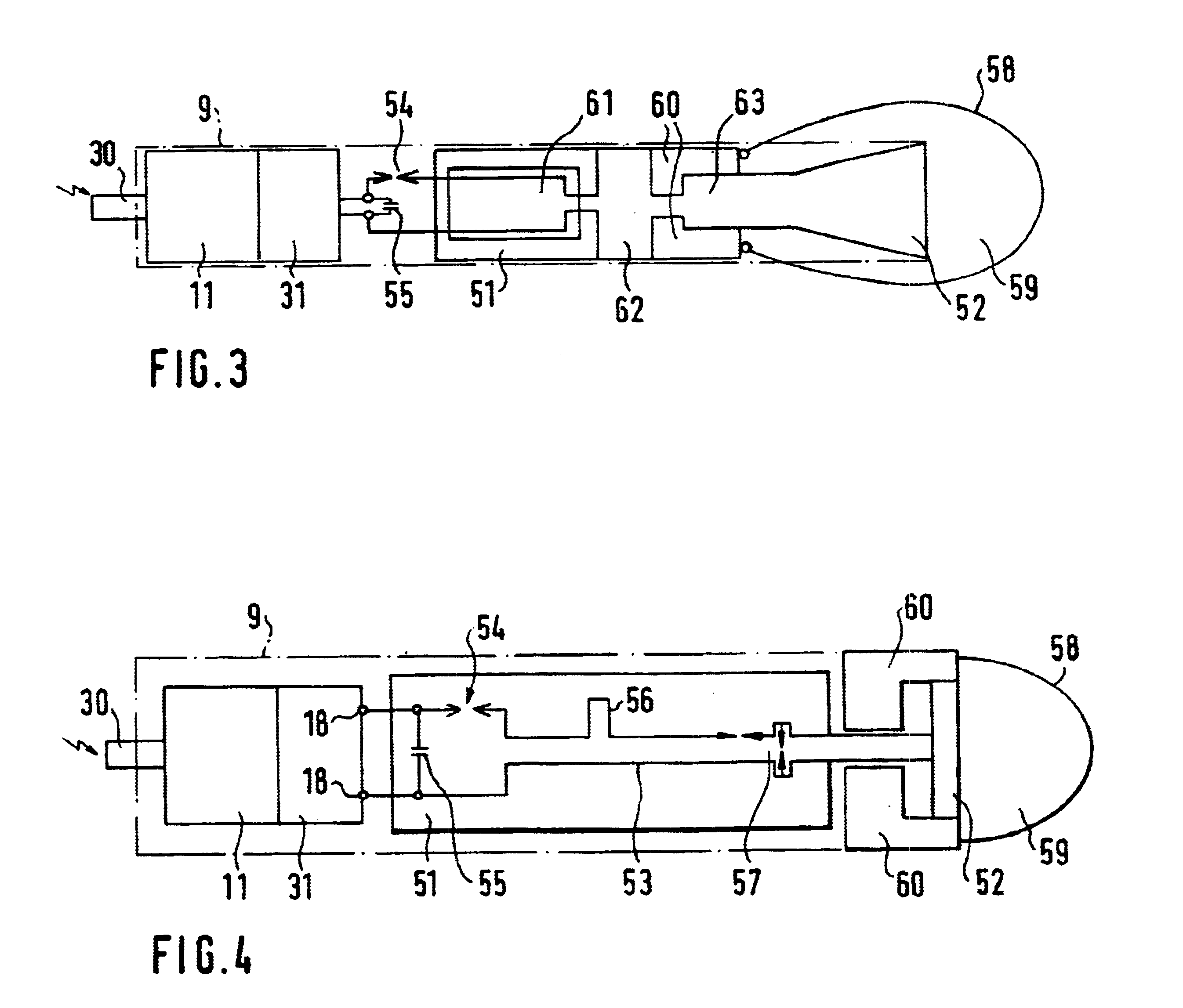
In the two first mentioned instances a detonation-operated magneto-hydrodynamic system which is located on board of the active body serves as an electrical pulse generator, whereas within the framework of the present invention description where must be taken into consideration for the detonation operation, propellent charge materials, as well as explosives materials. For current amplification and exciting oscillations, that pulse generator has a similarly detonation-operated magnetic field compressor connected to the output thereof which compressor is to act radially on the center axis, and which irreversibly reduces the cross-sectional surface of a cylindrical coil which is just to be streamed through by the pulse current from the generator.
The pulse generator and the current amplifier are preferably assembled space-savingly coaxially behind each other, however, partially overlapping each other, in effect, axially interengaging, so as to be able to upon the triggering of the one functional element to be able to concurrently trigger through to the other, and to achieve a compact and resultingly lighter-weight deployable active body. The coaxial cable or respectively, hollow conductor for pulse shaping can be wound about the pulse generator, whose diameter is typically smaller than that of a current amplifier, and also smaller than that of the antenna, so that the antenna itself, in the interest of obtaining an axially short construction of this active body, at an expedient electrical degree of efficiency of its functional components, can be axially slid most closely against the pulse generator.

Problems solved by technology

With regard to the grenade constructed pursuant to the U.S. Pat. No. 5,192,827, prior to the firing, an internal electrical energy storage battery or accumulator is charged in the barrel or launch tube from an external current source, wherein the accumulator is then discharged upon reaching the object which is to be disrupted, by means of a spark gap, and thereby as a result generates high-frequencies disturbances.
However, the power which is available for this purpose, in accordance with the behavior of the current source and the energy accumulator or battery, is extremely limited, and the loss or ohmic resistance of the capacitive charge accumulator, necessitates an excessively large capacitive time constant with regard to the sought after discharge time behavior over the spark gap.

Method used


Image

  • Non-lethal electromagnetic active body
  • Non-lethal electromagnetic active body
  • Non-lethal electromagnetic active body

Examples


Embodiment Construction

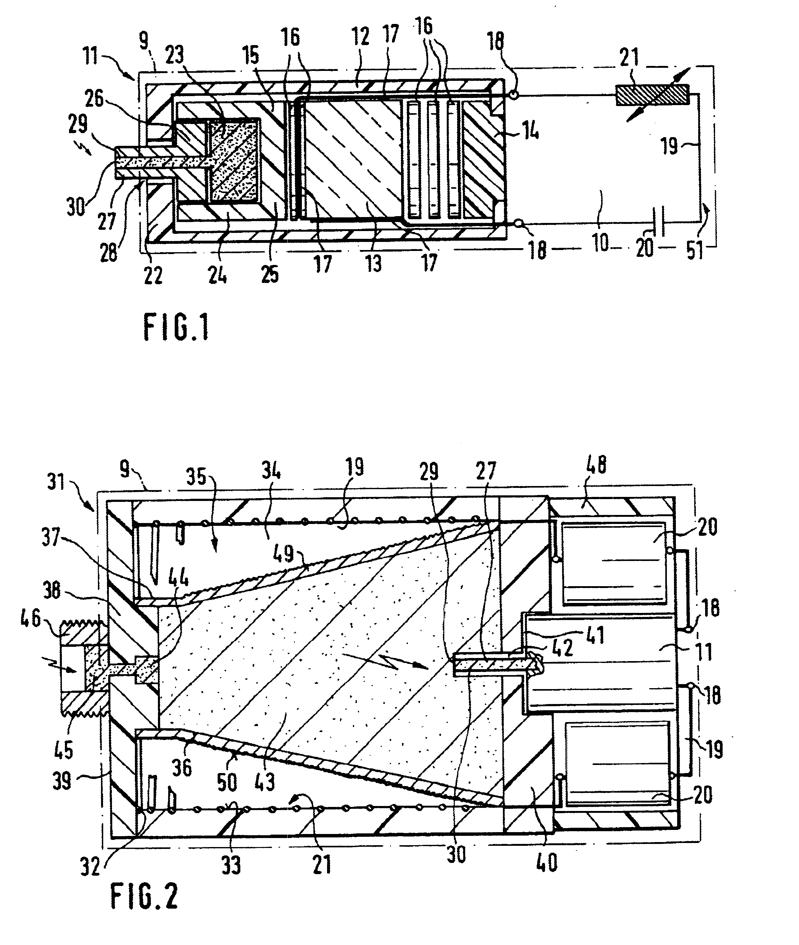
For the non-lethal electromagnetic active body 9 which is illustrated in FIG. 1 in an axial longitudinal cross-section, a current amplifying pulse transformer modulator 10 is supplied by a detonation-operated piezo-pulse generator 11. The latter, in the instance of the represented axial excitation provides within an encasing tube or shell 12, a square or short cylindrical piezo-crystal 13 located between a supporting mass 14 and an activating mass 15. Arranged between the piezo crystal 13 and the masses 14 and 15 which support the former on both sides thereof, in this axial design there are provided disc-shaped shock absorbers 16, preferably consisting of a material, such as acrylic glass, in order to prevent a mechanical destruction of the piezo-crystal 13 at already the build-up of the steep mechanical voltage peak at the beginning of the compression of the piezo crystal. By means of electrodes 17 which contact against the sides of the piezo-crystal 13, there is tapped off the cha...


PUM


Abstract

A non-lethal active body which is equipped with a detonation-operated electrical pulse generator, and which is especially deployable as an article of submunition. The pulse generator is a piezo-generator having a detonation-operated inductive current amplifier and a capacitive pulse shaper connected to the output thereof.

Description

1. Field of the InventionThe present invention relates to a non-lethal active body which is equipped with a detonation-operated electrical pulse generator, and which is especially deployable as an article of submunition.2. Discussion of the Prior ArtAn active body of that type is known as a microwave disrupter which is utilized for influencing the functioning of generally signal communications or guidance and control installations. The active body can be deployed as an article of submunition in accordance with the disclosure of European Patent Publication EP 075 572 24 A1, installed as a lurking mine pursuant to German Patent Publication DE 19 528 112 C1, or fired as a grenade in accordance with the disclosure of U.S. Pat. No. 5,192,827. With regard to the grenade constructed pursuant to the U.S. Pat. No. 5,192,827, prior to the firing, an internal electrical energy storage battery or accumulator is charged in the barrel or launch tube from an external current source, wherein the ac...

Claims


Application Information

Patent Timeline
Patent Type & Authority Patents(United States)
IPC IPC(8): F42B12/36F42B12/02
CPCF41H13/0093F42B12/36F42C11/02
Inventor BOHL, JURGENEHLEN, TILO
Owner DIEHL BGT DEFENCE GMBH & CO KG
Why Eureka
Try Eureka