
Programmable matrix switch

a matrix switch and switch technology, applied in the field of switch mechanisms, can solve the problems of increasing the risk of network failure, time-consuming and difficult work, and reducing the likelihood of having to repair the backplan

Inactive Publication Date: 2004-01-20
STORAGE TECHNOLOGY CORPORATION
View PDF21 Cites 83 Cited by
  • Summary
  • Abstract
  • Description
  • Claims
  • Application Information

AI Technical Summary

Problems solved by technology

This, of course, can be a time consuming and difficult job.
In addition, physically disturbing the cables and the interconnections increases the risk that network failures will occur.
Since active components are more often the cause of system failures, keeping active components off of the backplane greatly reduces the likelihood of having to repair the backplane.
In general, repairs to backplanes typically remove the system from service for a significant period of time.
The use of the passive backplane greatly reduces the likelihood that repairs will ever have to be done to the backplane.

Method used


Image

  • Programmable matrix switch
  • Programmable matrix switch
  • Programmable matrix switch

Examples


Embodiment Construction

)

Structure and Operation

I. Overview

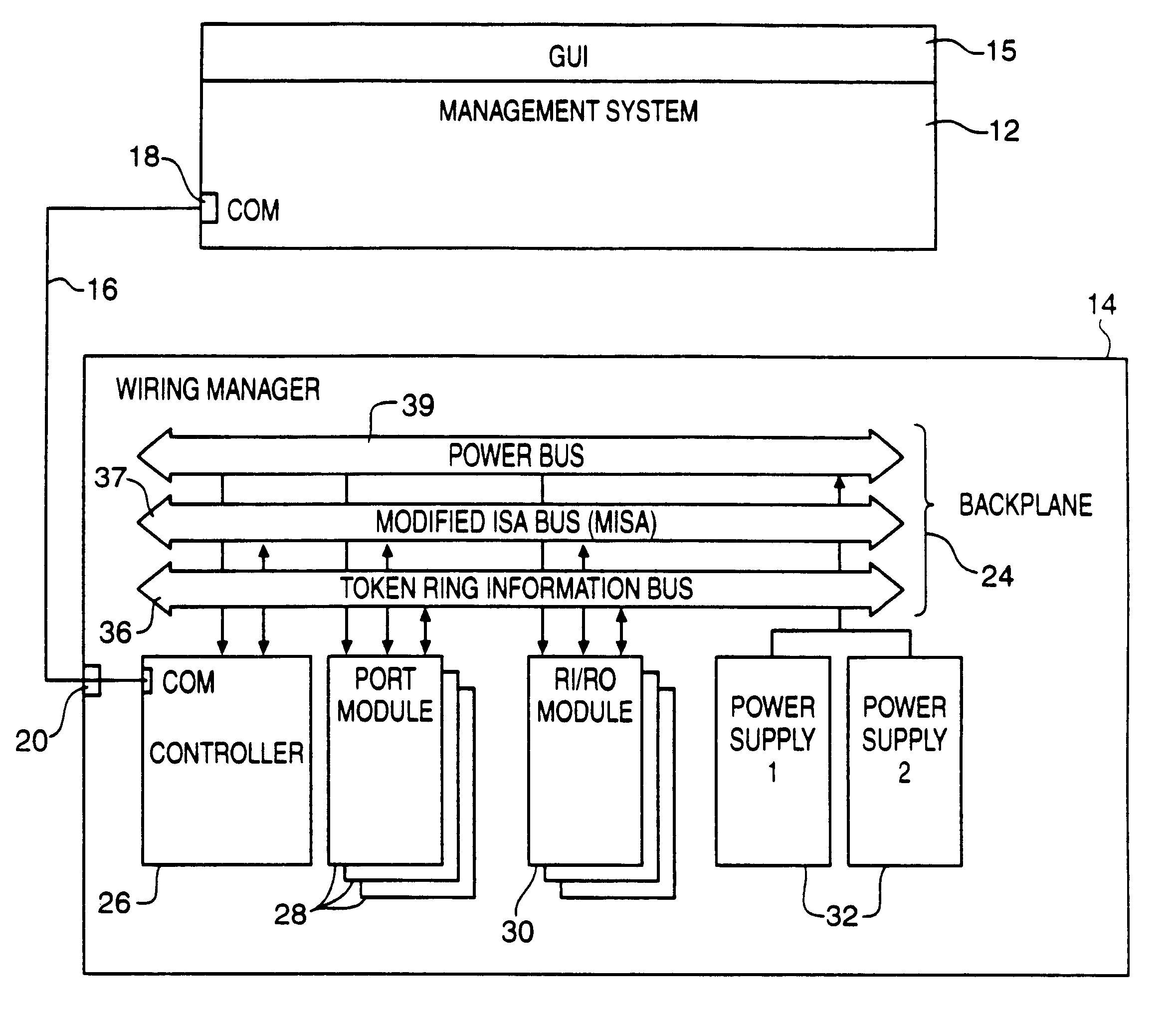
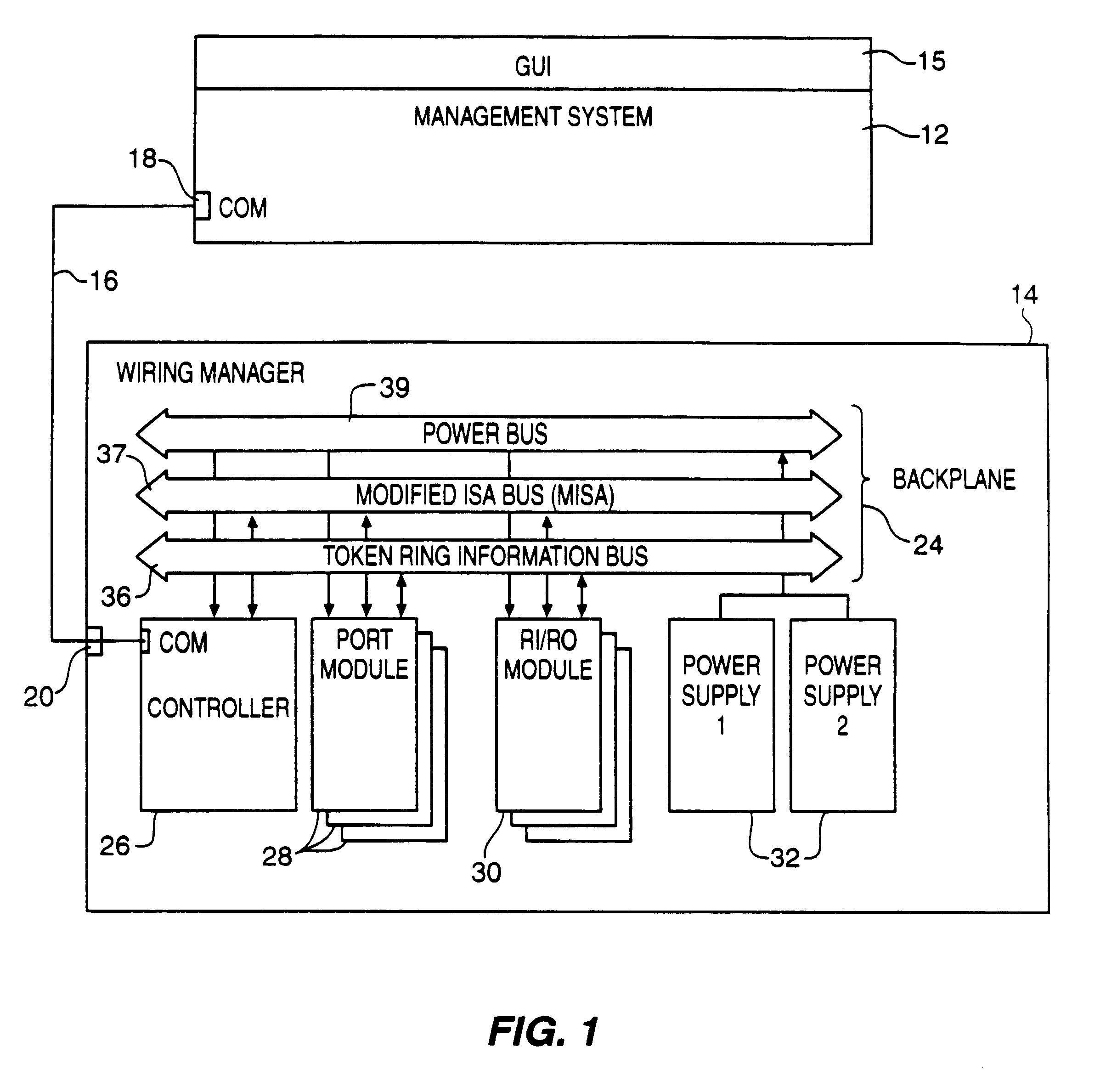
Referring to FIG. 1, a system for configuring and managing a Local Area Network (LAN) includes two components, namely, a LAN management system (LMS) 12 and a wiring manager 4. LMS 12 handles the higher level management functions of the system and provides a graphical user interface (GUI) 15 based on X Windows.TM. and Motif.TM., which displays connection and network status information to the user and enables the user to communicate commands to LMS 12 and wiring manager 14. Additional details regarding LMS 12 may be found in U.S. application Ser. No. 07 / 744,295, filed on Aug. 13, 1991, now abandoned and incorporated herein by reference.

LMS 12 and wiring manager 14 communicate with each other over a dedicated line 16 using an asynchronous serial communications protocol. LMS 12 and wiring manager 14 each have a communication port 18 and 20, respectively, which supports the communication. LMS 12, which can manage more than one wiring manager, communicat...


PUM


Abstract

A system and method for interconnecting a plurality of network components to form a local area network (LAN) include a wiring manager having at least one port module connected to a controller via a data signal bus on a passive backplane. Each port module includes a plurality of ports which can be programmed to electrically couple selected sets of the plurality of network components without physically rerouting network cabling. A LAN management system provides a graphical user interface to communicate with the wiring manager and provide network status information and control the wiring manager to configure the network.

Description

1. Field of the InventionThe invention relates to an apparatus for managing a local area network, in particular, it relates to a switching mechanism that is used to manage the physical layer of a local area network.2. Background ArtLocal area networks (LANs) provide a popular, cost effective way of interconnecting many computing resources (e.g. personal computers, minicomputers or workstations) within an enterprise. The backbone of the LAN is a wiring system that provides a physical transmission medium for interconnecting the computing resources. The wiring system may be coaxial cable, shielded or unshielded copper wire, or fiber optic cable. For each computing resource there is a transceiver that provides the electrical connection or interface between the computing resource and the wiring system. The transceiver converts the information from the computing resource into the actual signals that propagate over the wiring system. The LAN also includes network software which assembles t...

Claims


Application Information

Patent Timeline
Patent Type & Authority Patents(United States)
IPC IPC(8): H04L12/56
CPCH04L49/102H04L49/101H04L49/351H04L49/357
Inventor MANCUSI, MICHAEL D.MASSERY, JOSEPH E.OSMOND, ROGER F.FITZGERALD, MICHAEL J.
Owner STORAGE TECHNOLOGY CORPORATION
Learn More