Wire puller

a wire puller and wire technology, applied in the field of wire pullers, can solve the problems of insufficient use, insufficient weight, and the need to substitute machine force for human force in pulling wire without significant bulk, and achieve the effect of minimizing the weight and cost of the apparatus

Inactive Publication Date: 2004-01-27
SOUTHWIRE CO LLC
View PDF22 Cites 39 Cited by
  • Summary
  • Abstract
  • Description
  • Claims
  • Application Information

AI Technical Summary

Benefits of technology

It can be seen from the above discussion that it would be an improvement in the art to provide a line puller which can be driven by a multiple use motor so that the weight and cost of the apparatus is minimized

Problems solved by technology

Each of the named apparatus includes a dedicated motor; however, dedicating a motor in most cases adds bulk, weight, and cost.
Therefore, the need to substitute machine force for human force in pulling wire without significant bulk, weight, and cost is not met by these apparatus.
However, they are often insufficient for use with the various weights an

Method used


Image

  • Wire puller
  • Wire puller
  • Wire puller

Examples


Embodiment Construction

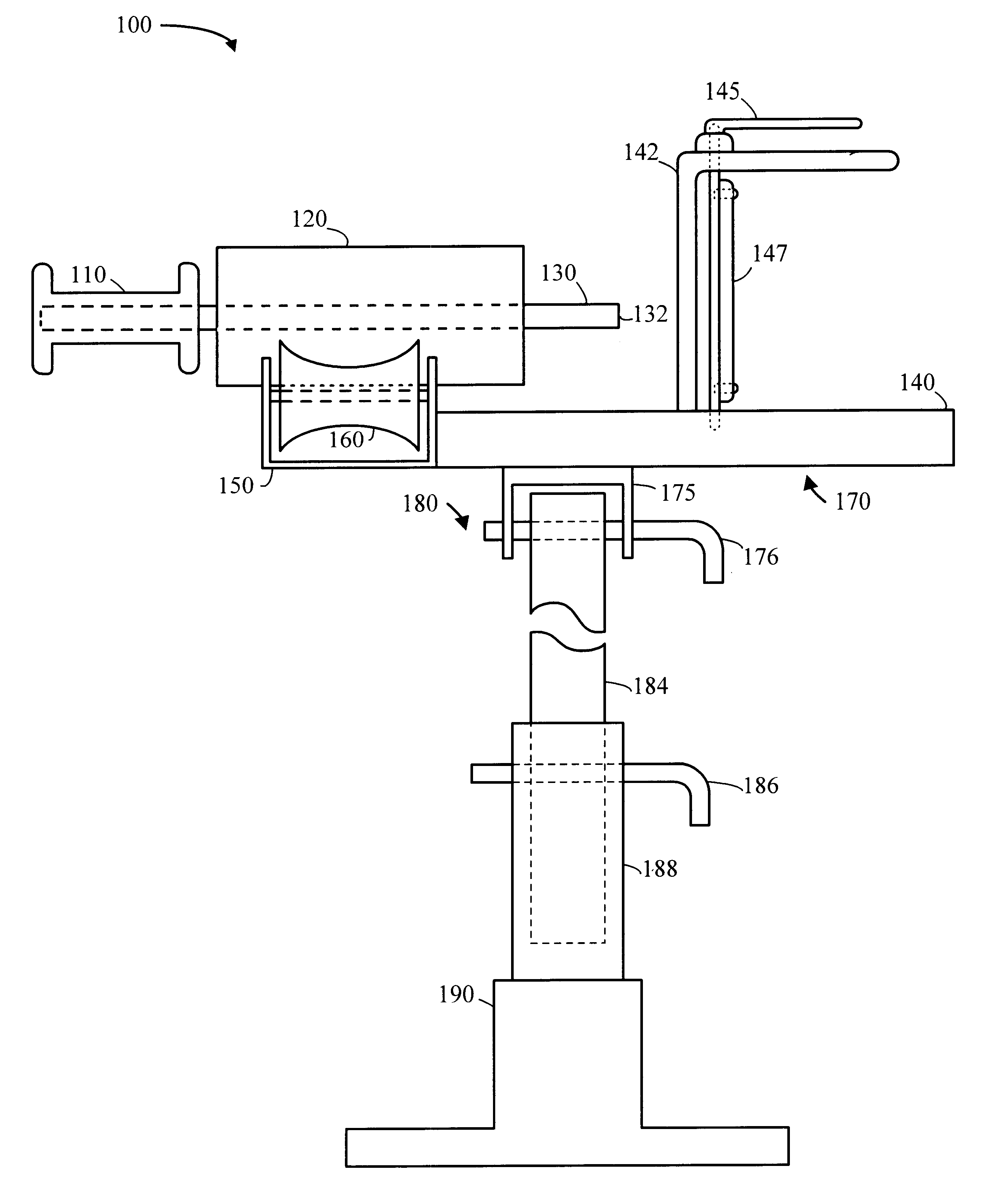
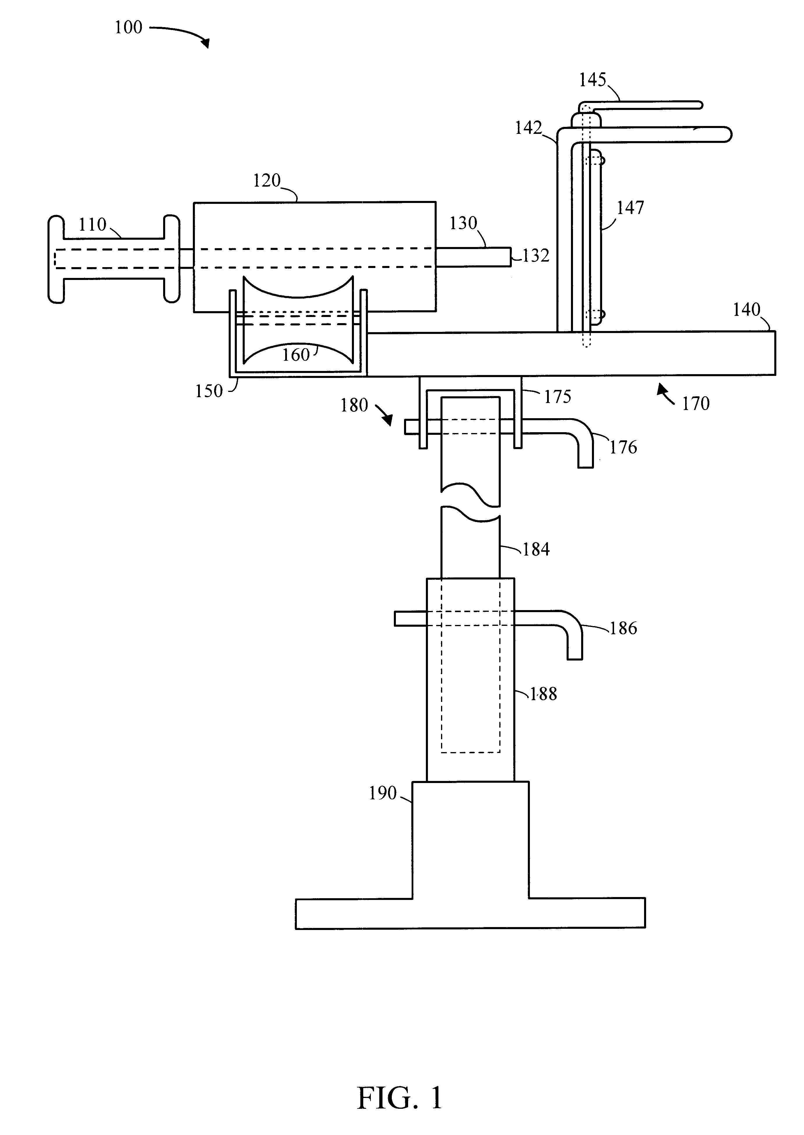
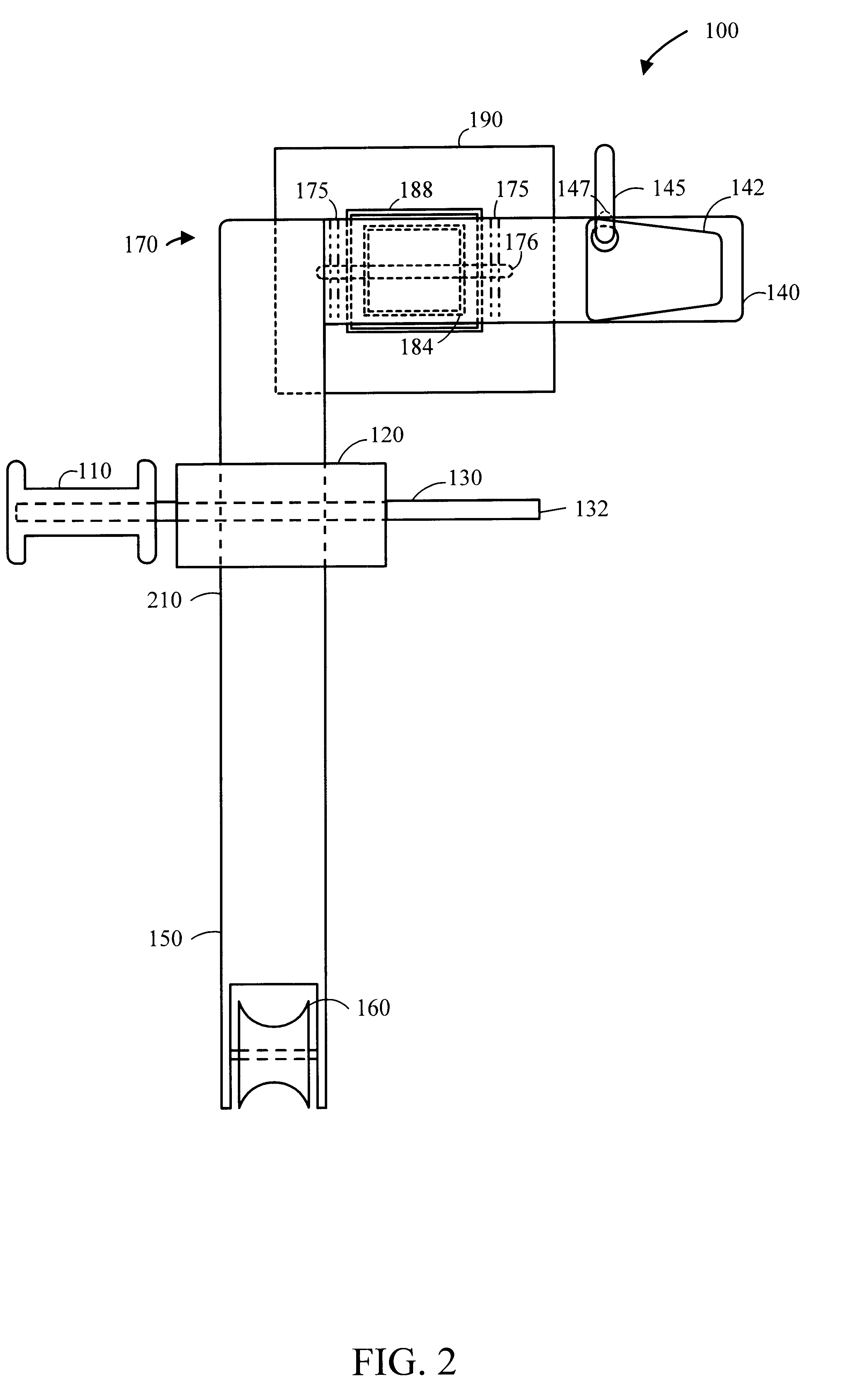
According to an embodiment of the present invention, a wire puller that utilizes the motor force of a standard right-angle power drill is disclosed. However, those skilled in the art will appreciate that any of several portable rotary power tools, such as power wrenches, can be used with the present invention. The wire puller can be operated by a single operator and disassembled to fit into a hand-held case. The hand-held case for the embodiment shown in FIGS. 1-3, measuring approximately 12 inches wide, by 21 inches long, by 7 inches high, facilitates transport of the wire puller to a location where line is to be pulled. A typical location at which line is pulled is a junction box at the end of a length of conduit. The wire puller is assembled in close proximity to the junction box.

Assembly of the wire puller shown in FIGS. 1-3 includes the steps of attaching the wire puller frame to its stand, resting the forearm frame portion of the wire puller on the junction box opening, positi...


PUM


Abstract

An apparatus includes a frame having a drive shaft mounting portion, a power tool restraint portion, and an adjustable forearm portion, wherein the power tool restraint portion is adapted to register a portable rotary power tool with the frame. A drive shaft is mounted with the frame in the drive shaft mounting portion, wherein the drive shaft is sized to be coupled with a rotary output of the power tool. A mounting bracket having arms ending in angled arm ends to facilitate the use of the apparatus in confined spaces is adjustably mounted to the forearm portion. An adapter set includes at least two adapters of differing sizes that may be removably attached to the mounting bracket and used to supply a force to the structure through which the line is being pulled that opposes the force on the structure produced by the line itself, thus stabilizing the structure.

Description

1. Technical FieldThis invention relates to the field of an apparatus for applying pulling force. More specifically the invention relates to an apparatus for the placement of conductive wire.2. Background ArtSupplying buildings with electricity and communications capabilities involves threading lines, or cable, through conduit. Typically, the path that cable must travel through the conduit includes changes in elevation and turns around corners. Generally, the procedure used to run cable involves first threading lightweight flexible lines through the entire length of conduit. Heavier lines are then pulled through, by attaching them to one end of the lighter line and pulling the lighter line through at the other end of the conduit. This procedure may need to be repeated until a line is threaded which can bear the weight of the target cable, when is then attached and pulled through.To thread heavier lines, lighter lines must be pulled through first. The pulling force required can be si...

Claims


Application Information

Patent Timeline
IPC IPC(8): B65H51/06B65H51/00H02G1/08
CPCB65H51/06H02G1/08
Inventor RAY, BRIAN N.
Owner SOUTHWIRE CO LLC
Why Eureka
Try Eureka