Optical member inspection apparatus, image-processing apparatus, image-processing method, and computer readable medium

an inspection apparatus and optical member technology, applied in the direction of optical apparatus testing, structural/machine measurement, instruments, etc., can solve the problems of inability to obtain desired performance, inability to evaluate the difference of degree of defects between such optical members, scattered incident light flux,

Inactive Publication Date: 2004-02-03
ASAHI KOGAKU KOGYO KK
View PDF7 Cites 35 Cited by
  • Summary
  • Abstract
  • Description
  • Claims
  • Application Information

AI Technical Summary

Problems solved by technology

However, if the optical member contains therein a foreign matter such as a cotton waste or the like (so called "fuzz"), due to a defective formation thereof, or if the surface of the optical member is scratched when handled by operator after molding thereof, or if foreign matter is affixed to the surface of the optical member, the incident light flux will be scattered, and the desired performance cannot be obtained.
However, in accordance with the algorithm of the above-mentioned conventional judgement, the information obtained as a result of the inspection merely points out whether the inspection target optical member is satisfactory or defective.
But, the aforementioned conventional algorithm of judgement cannot evaluate the difference of degree of defects between such optical members because of the above-mentioned reason.
Thus, in accordance with the conventional algorithm of judgement, the degree of defects of the inspection target optical members cannot be evaluated.

Method used


Image

  • Optical member inspection apparatus, image-processing apparatus, image-processing method, and computer readable medium
  • Optical member inspection apparatus, image-processing apparatus, image-processing method, and computer readable medium
  • Optical member inspection apparatus, image-processing apparatus, image-processing method, and computer readable medium

Examples


first embodiment

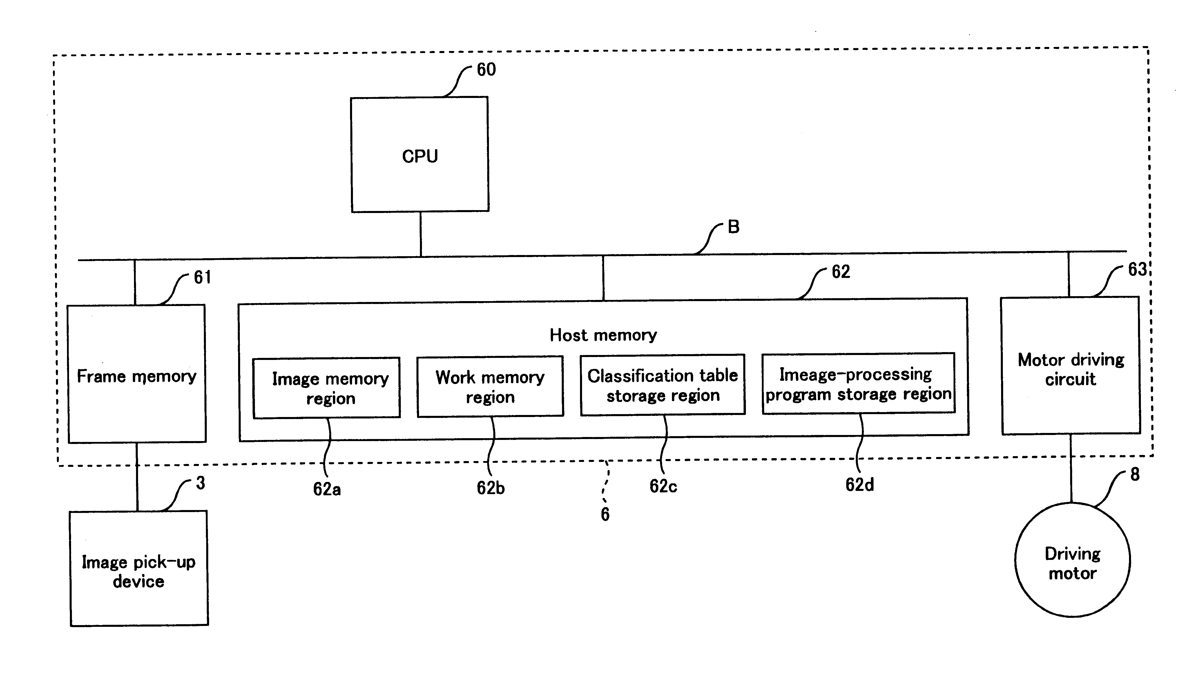
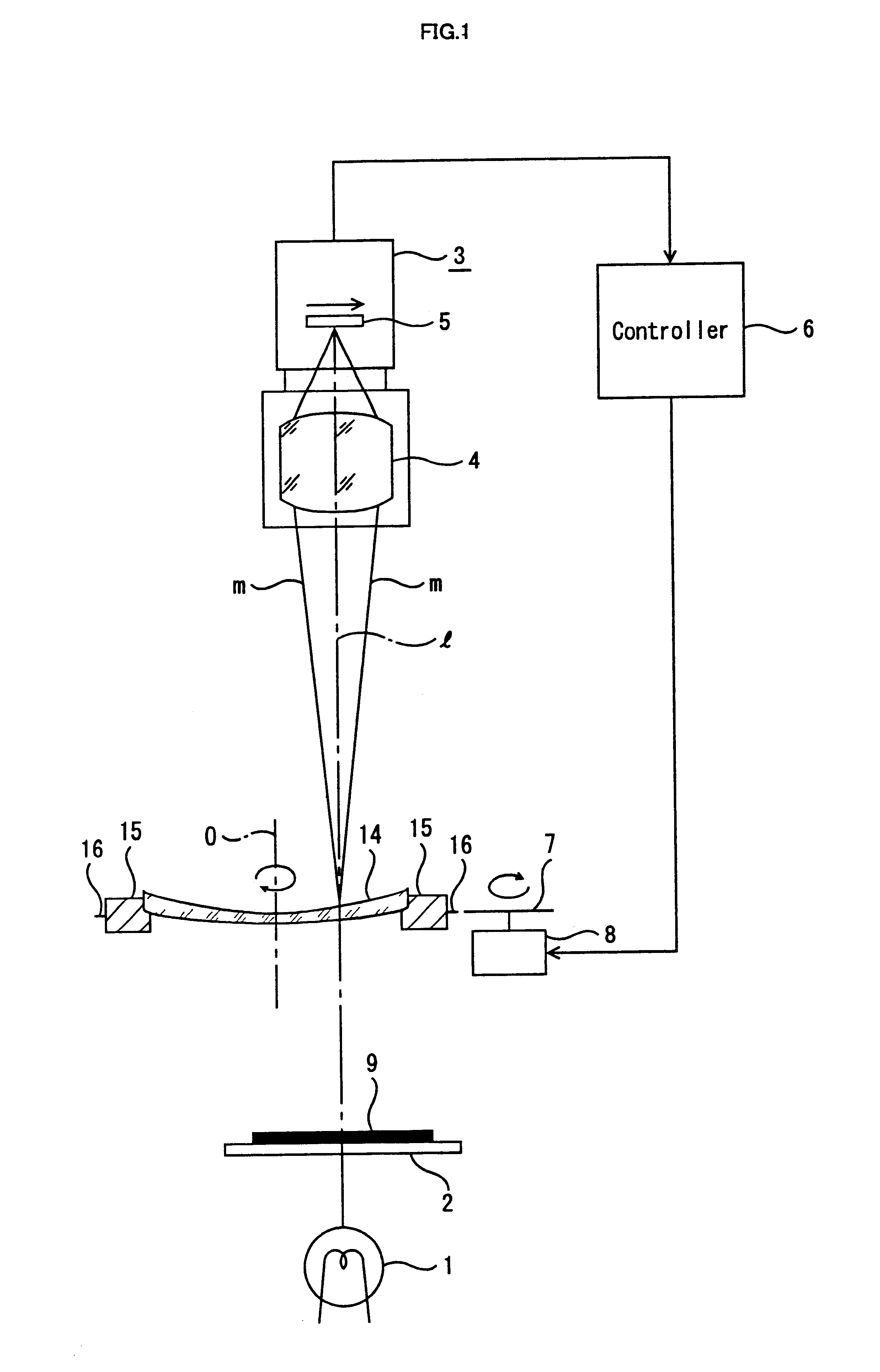
A schematic structure of optical member inspection apparatus according to the present invention is shown in FIG. 1. As shown in FIG. 1, the illumination lamp 1, diffusion plate 2, and the image pick-up device 3 which compose the optical member inspection apparatus, are all aligned on a common optical axis 1. The image pick-up device 3 includes an imaging lens 4 which is a positive lens system, and the CCD line sensor 5 which picks up the image formed from light converged by the imaging lens 4. The CCD line sensor 5 is set in the image pick-up device 3 so that row of pixels consisting the CCD line sensor 5 is oriented to horizontal direction in FIG. 1. Furthermore, the row of the pixels of the CCD line sensor 5 perpendicularly intersects with the optical axis 1 of the imaging lens 4 at the central portion. In addition, the imaging lens 4 is held in the image pick-up device 5 so that it can freely move for focusing with respect to the CCD line sensor 5. The image pick-up device 3 itse...

second embodiment

In comparison with the first embodiment, the optical member inspection apparatus according to the second embodiment of the present invention is different only in construction in the host memory 62, and in the contents of control processing executed by CPU 60 in accordance with the image-processing program which is stored in the image-processing program storage region 62d of this host memory 62. The all other construction of the second embodiment are same as the first embodiment.

The reason why this second embodiment was designed is as follows. According to the above mentioned first embodiment, only areas of each defective candidate object extracted through the binarization process are normalized on the basis of the reference values Rk and Rd, and the judgement whether the inspection target optical member is satisfactory or defective is made on the basis of the normalized area. Thus, if comparison is made between defective candidate objects having same area, it is judged that the degr...

third embodiment

In comparison with the above mentioned second embodiment, the optical member inspection apparatus according to the third embodiment of the present invention is different only in the content of control processing executed by CPU 60 in accordance with the image-processing program stored in image-processing program storage region 62d of the host memory 62. The remaining construction of the third embodiment are same as the second embodiment.

Principle of Quality Evaluation as to an Inspection Target Optical Member

Similar to the above-mentioned first embodiment, the CPU 60 controls of each part of the optical member inspection apparatus, transforms the coordinate system of the image data obtained by picking up the image of the inspection target optical member 14, from polar coordinate system to rectangular coordinate system, and copies the image data formed on the first work memory region 62e through the coordinate transformation to the second work memory region 62f. Subsequently, the CPU...


PUM

PropertyMeasurementUnit
brightnessaaaaaaaaaa
distanceaaaaaaaaaa
optical member inspection apparatusaaaaaaaaaa

Abstract

The image pick-up device picks up an image of the inspection target optical member whenever it rotates a predetermined angle. The image data which is output by the image pick-up device picking-up the image undergoes coordinate transformation from polar coordinate system to rectangular coordinate system and thereafter binarization process. The area of the defective candidate objects which are extracted from the image data in two color system obtained through the binarization process are normalized in accordance with the reference values prepared for each region in which said defective candidate objects formed within the image data. The points which are calculated as a result of this normalization, are added to the corresponding columns in the classification table. It is judged whether the inspection target optical member is satisfactory or not, in accordance with whether or not evaluation function calculated on the basis of the value in each column exceeds a predetermined reference value.

Description

1. Field of the InventionThe present invention relates to an optical member inspection apparatus, an image-processing apparatus, an image-processing method, and computer readable medium, for detecting an optical defect such as an abnormality in shape or the like, in an optical member such as a lens or the like.2. Description of the Related ArtAn optical member such as a lens or a prism, etc., is generally designed so that incident light flux is refracted regularly, advanced in parallel, converged onto a point or a line, or diverged. However, if the optical member contains therein a foreign matter such as a cotton waste or the like (so called "fuzz"), due to a defective formation thereof, or if the surface of the optical member is scratched when handled by operator after molding thereof, or if foreign matter is affixed to the surface of the optical member, the incident light flux will be scattered, and the desired performance cannot be obtained.Thus, hitherto, various improvements ha...

Claims


Application Information

Patent Timeline
Patent Type & Authority Patents(United States)
IPC IPC(8): G01B11/00G01M11/02G01N21/88G06K9/00
CPCG01M11/0257G01M11/0278
Inventor SUGIURA, MASAYUKIYAMAMOTO, KIYOSHINAKANISHI, TAICHI
Owner ASAHI KOGAKU KOGYO KK
Why Eureka
Try Eureka