Tractor-trailer viewing system

a technology of viewing system and tractor trailer, which is applied in the field of viewing system, can solve the problems of poor or blocked vision of the driver of the tractor-trailer motor vehicle of specific areas located behind and to the side of the tractor and trailer, and achieve the effect of improving the viewing system

Inactive Publication Date: 2004-02-10
MOORE MICHAEL S
View PDF17 Cites 262 Cited by
  • Summary
  • Abstract
  • Description
  • Claims
  • Application Information

AI Technical Summary

Benefits of technology

to provide an improved viewing system

Problems solved by technology

It is widely known that the vision of a driver of a tractor-trailer motor vehicle of specific areas located behind and to the sides of the tractor and trailer may be poor or blocked.
In fact, these specific areas, commonly known as "b

Method used


Image

  • Tractor-trailer viewing system
  • Tractor-trailer viewing system
  • Tractor-trailer viewing system

Examples


first embodiment

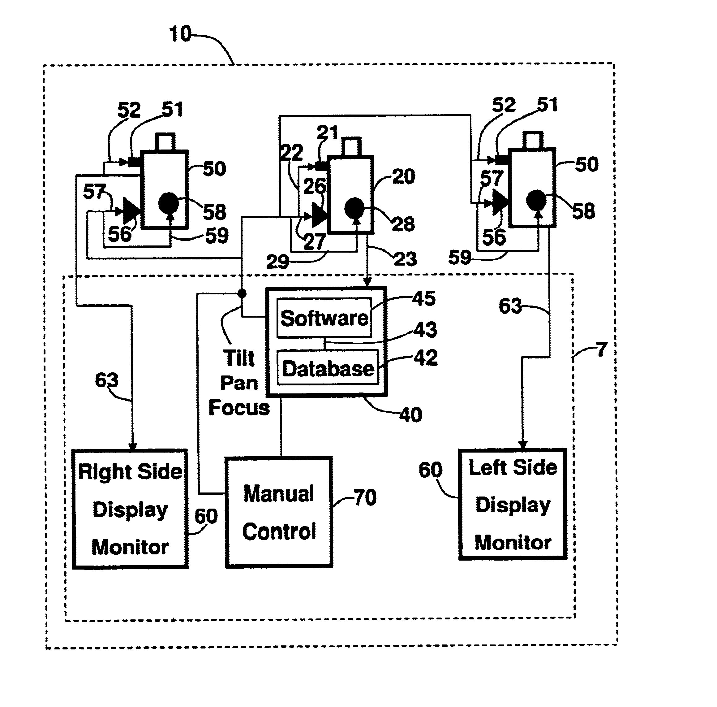
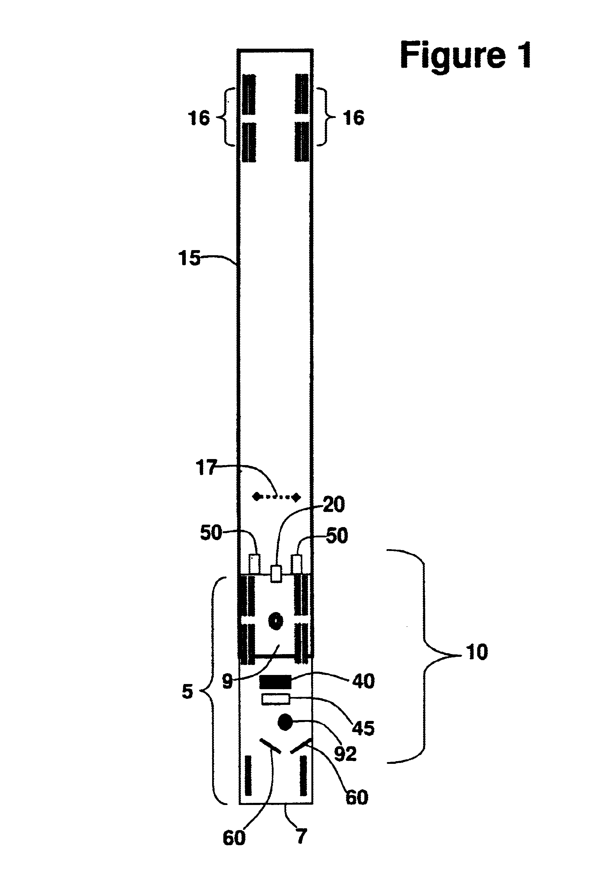
In the first embodiment shown in FIGS. 1, 3, and 4, the system 10 includes one centrally aligned image capturing camera 20 and two laterally positioned viewing cameras 50 all coupled to a computer 40. The computer 40 includes working memory that is loaded with an image capturing software program 45 and an image database 42 that contains a plurality of stored image files 43 of various trailer-related targeted objects. During operation, the image capturing camera 20 focuses on the targeted object, (rear tire 16 in FIG. 3), and transmits an actual image file, denoted 23, to the computer 40. An image file 43 is then selected from the image database 42 and used by the image capturing software program 45. When the actual image file 23 is transmitted to the computer 40, the image capturing software program 45 processes the actual image file 23 and compares it to the stored image file 43. If the actual image file 23 does not match the stored image file 43, the image capturing software progr...

second embodiment

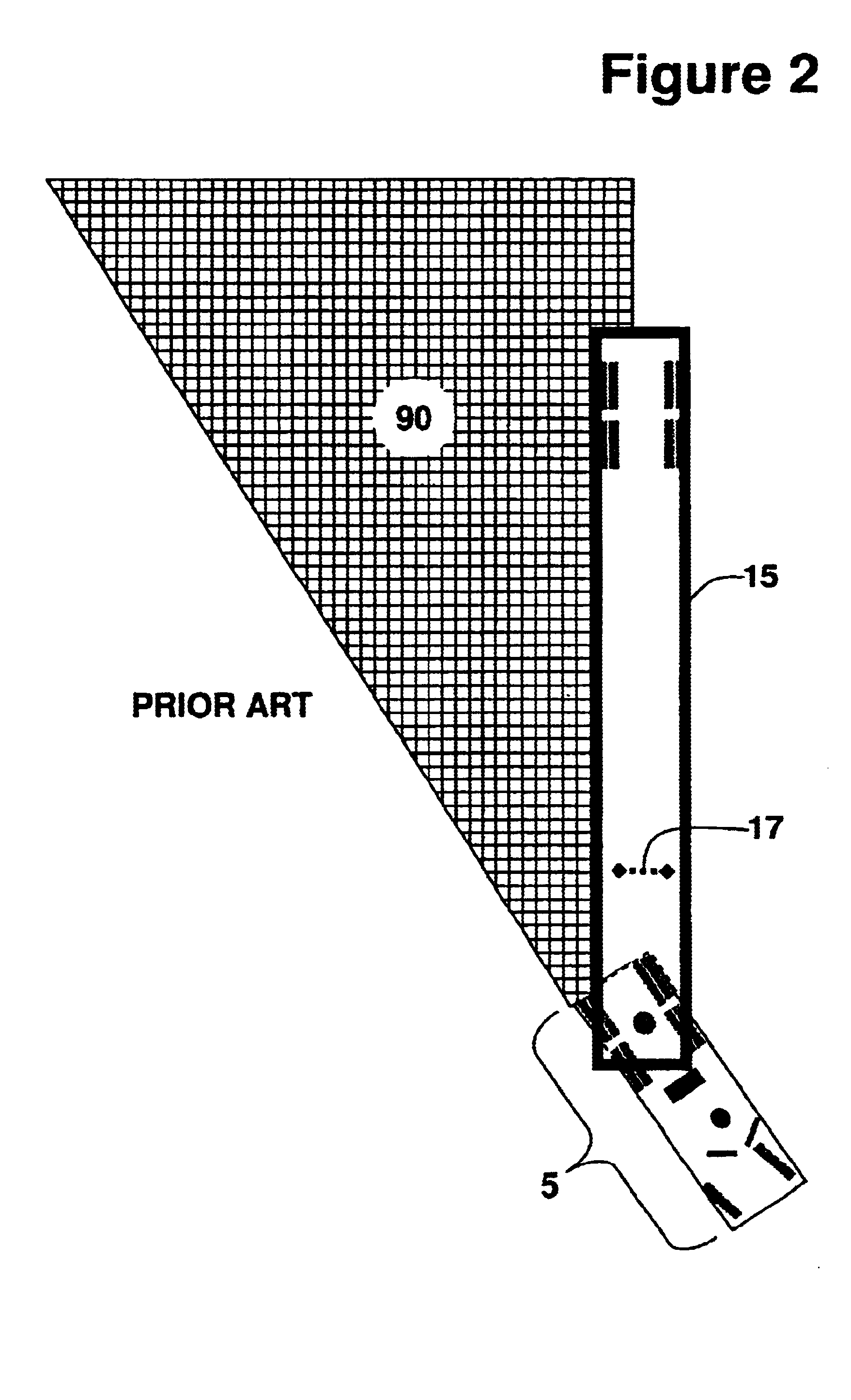
In FIG. 5, the system 10 is shown in which the functions of the image capturing device and a viewing camera are combined into one combination camera, denoted 20'. In this embodiment, actual image file 23 is transmitted both to the computer 40 and to the display monitor 60 located in the tractor 5. One drawback with this design is that it does not offer a good view of either side of the trailer 15 unless the tractor 5 is turned approximately 30 degrees or more. For this reason, when one image capturing camera 20 or one combination camera 20' is used, it is recommended that it focus a central undercarriage target, such as the landing gear 17 rather than the rear tire 16. When the image capturing camera 20 or combination camera 20' focuses on a rear tire 16, the tractor's landing gear 17 obscures the rearward view when the tractor 5 is turned approximately 60 degrees or more.

third embodiment

In a third embodiment shown in FIG. 6, two combination cameras 20' are used. Each combination camera 20' is rearward mounted and spaced apart on the rear transverse member on the tractor. Each combination camera 20' is coupled to the computer 40 and to a display monitor 60 located on the same side of the tractor 5.

One or more display monitors 60 are provided that should be mounted close to, and within easy viewing range of the driver. These display monitors 60 should be positioned to the left and right of the driver, with the left display monitor always showing views of the viewing camera 50 mounted on the left side of the motor vehicle, and the right display monitor 60 always showing views of the right side of the motor vehicle. Mounting the display monitors 60 in this manner maintains the natural tendency for the driver to look to the left for left-side views, and to the right for right-side views, similar to using standard vehicle mirrors. The image capturing software program 45 ...


PUM


Abstract

This invention relates to motor vehicles, and, more particularly, to a rear viewing system for tractor-trailer vehicles. An automated, universal trailer rear viewing system that is integrated in its entirety on the head or pulling portion of a pivotally connected articulated vehicle. The system includes: (a) at least one image capturing device mounted on the tractor designed to tilt, pan and focus on a target object or an area around the trailer; (b) a computer located inside the tractor coupled to the image capturing device; (c) an image capturing and comparative software program loaded into the memory of the computer capable of processing the image file of the target object transmitted from the image capturing device, and capable of generating control commands to the image capturing device so that an image of the target object is maintained as the system is activated; (d) at least one adjustable viewing camera also coupled to the computer that automatically adjusts the viewing camera tilting, panning and focusing according to the movement of the image capturing device; and, (e) at least one display monitor located near the driver that is coupled to the viewing camera so that the image seen thereby may be seen by the driver.

Description

1. Field of the InventionThis invention relates to viewing systems used on motor vehicles, and, more particularly, to a rear and side viewing system for heavy tractor-trailer motor vehicles.2. Description of the Related ArtIt is widely known that the vision of a driver of a tractor-trailer motor vehicle of specific areas located behind and to the sides of the tractor and trailer may be poor or blocked. In fact, these specific areas, commonly known as "blind spots", are a major cause of accidents involving tractor-trailer motor vehicles. Visibility of these areas is especially important when turning the motor vehicle sharply to the left or right and when backing up, as shown in FIG. 2. Since many tractor-trailer motor vehicles are driven without a second individual acting as a guide or spotter to assist the driver, drivers are often required to turn or back up their tractor-trailer motor vehicles without actually knowing if an object, such as another motor vehicle or an individual, i...

Claims


Application Information

Patent Timeline
IPC IPC(8): B60R1/02B60R1/00H04N7/18
CPCB60R1/00B60R1/025H04N7/181H04N7/188B60R2300/101B60R2300/105B60R2300/30B60R2300/802B60R2300/8066
Inventor MOORE, MICHAEL S.
Owner MOORE MICHAEL S
Why Eureka
Try Eureka