Lokring fitting having improved anti-torsion capability

a technology of torsion capability and fitting, which is applied in the direction of sleeve/socket joint, mechanical apparatus, manufacturing tools, etc., can solve the problems of not being particularly suitable for resisting, and achieve the effect of improving torsion capability

Inactive Publication Date: 2004-02-17
LOKRING TECHNOLOGY
View PDF7 Cites 59 Cited by
  • Summary
  • Abstract
  • Description
  • Claims
  • Application Information

AI Technical Summary

Benefits of technology

It is therefore one of the primary objects of the present invention to provide a fluid fitting having improved torsion capabilities.

Problems solved by technology

The isolation tooth arrangement in this patent appears to have some merit for protecting the seals from bending moments, but inasmuch as the isolation gripping teeth run circumferentially, they are not believed to be particularly suitable for resisting torsion about the axis of the pipe.

Method used


Image

  • Lokring fitting having improved anti-torsion capability
  • Lokring fitting having improved anti-torsion capability
  • Lokring fitting having improved anti-torsion capability

Examples


Embodiment Construction

, particularly, when the detailed description is taken in conjunction with the attached drawing figures and with the appended claims.

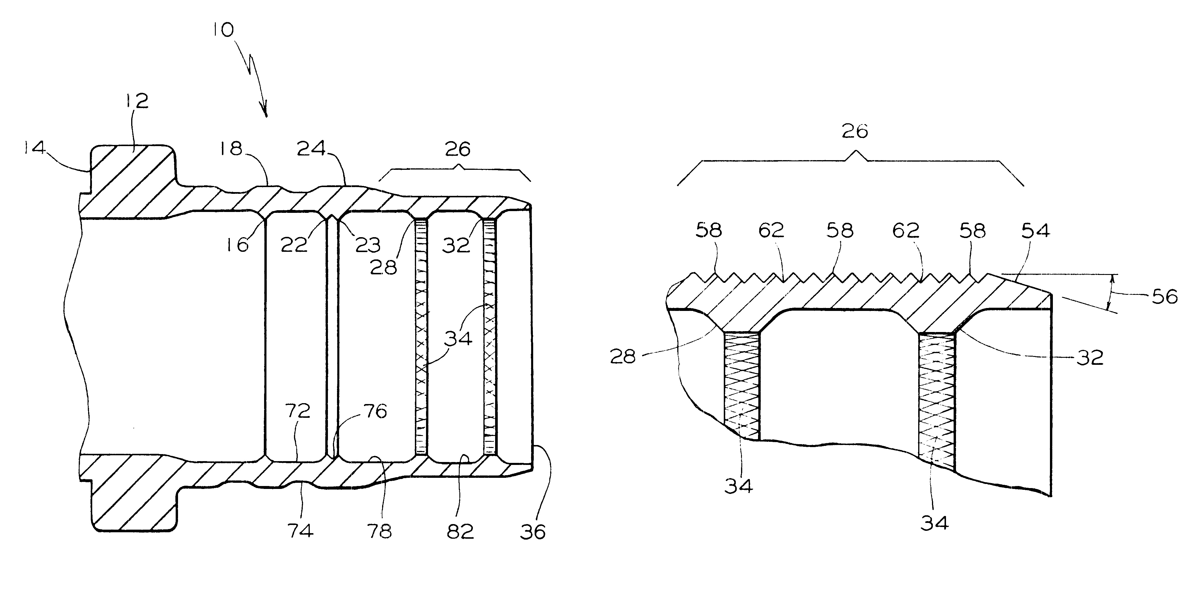
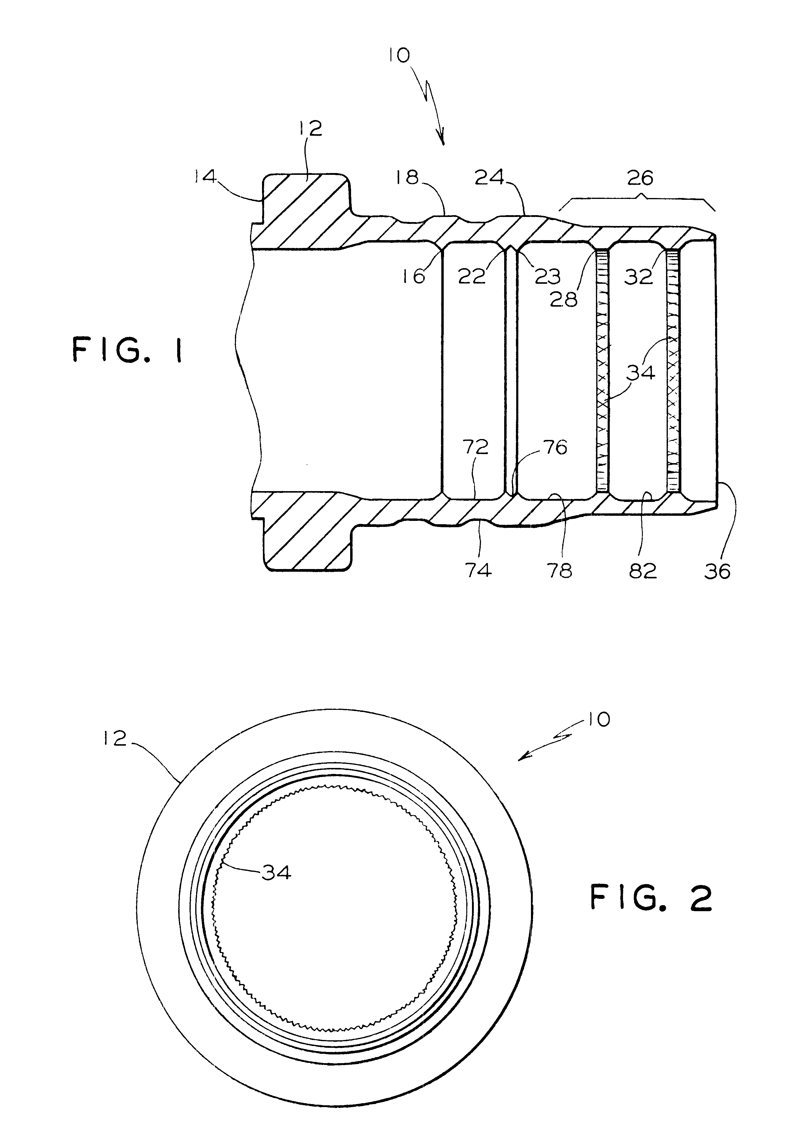
FIG. 1 is a longitudinal median section of the coupling body, according to the present invention.

FIG. 2 is an end view of the coupling body.

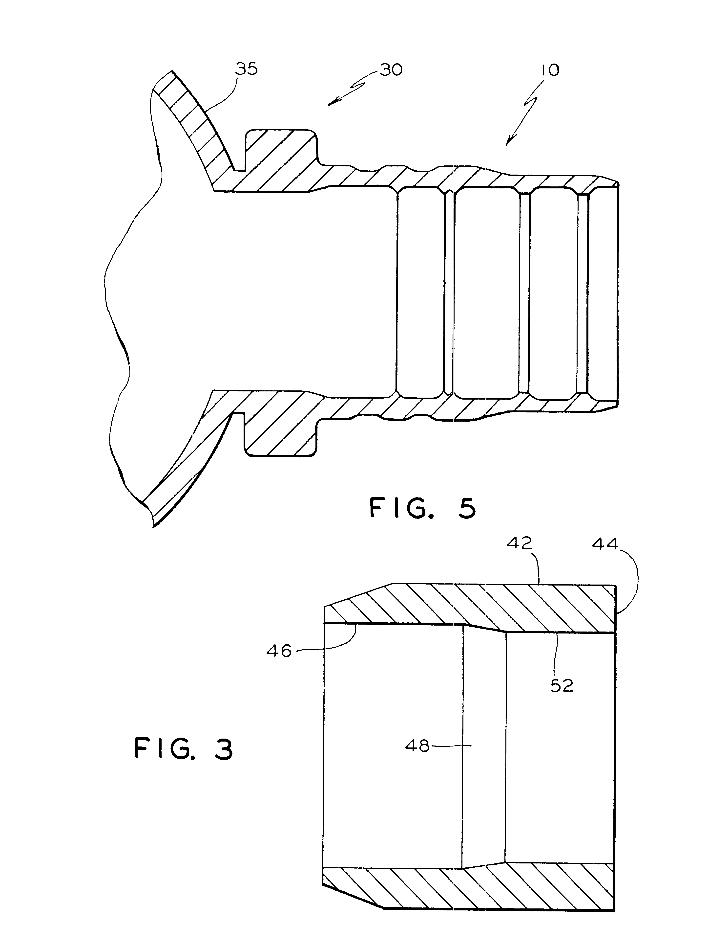
FIG. 3 is a swage ring which provides inward compression of the coupling body.

FIG. 4 is a coupling body for joining a pair of like tubes or pipes, according to the present invention.

FIG. 5 is a coupling body formed integrally with a housing of a fluid pressure device.

FIG. 6 is a detail drawing of a portion of the distal end of the coupling body.

BRIEF DESCRIPTION OF THE PRESENTLY PREFERRED AND VARIOUS ALTERNATIVE EMBODIMENTS OF THE INVENTION

Prior to proceeding to the much more detailed description of the present invention, it should be noted that identical components which have identical functions have been identified with identical reference numerals throughout the several views illustrated in the drawing figures f...


PUM

PropertyMeasurementUnit
taper angleaaaaaaaaaa
forceaaaaaaaaaa
pressureaaaaaaaaaa

Abstract

A fitting for a fluid pressure conduit. The fitting includes a coupling body having a substantially axisymmetrical inside surface for engaging an outside surface of the fluid pressure conduit. The inside surface has at least one substantially axisymmetrical seal formed as at least one axisymmetrical ridge on the inside surface of the coupling body. There is at least one seal land on an outside surface of the coupling body adjacent the substantially axisymmetrical seal(s). There are a plurality of anti-torsion ridges on the inside surface of the coupling body, the anti-torsion ridges having friction surfaces for resisting torsion between the fitting and the fluid pressure conduit. Furthermore, there is at least one torsion land formed on the outside surface of the coupling body adjacent the torsion ridges. The fitting also includes a ring for fitting over the coupling body, the ring being for engaging the seal land(s) to force the seal(s) into engagement with the outside surface of the fluid conduit, the ring further being for engaging the torsion land(s) to force the plurality of anti-torsion ridges into engagement with the fluid pressure conduit.

Description

The present invention relates, in general, to fluid fittings and, more particularly, the instant invention relates to LOKRING.RTM. fittings.Various types of fittings have been developed for joining tubes and pipes to other tubes and pipes, or to fluid apparatus such as pumps, fluid motors, and actuation cylinders. For thin walled tubing or pipe, various types of fittings are used which compress against the outside diameter of the tube or pipe to create a seal. One particular type of fitting includes a swage ring which is forced over the fitting to compress it radially inward against the tube or pipe. Generally, this type of fitting has one or more circumferential ridges on its I.D. which, when compressed inwardly by the swage ring, engage the O.D. of the tube or pipe to create one or more circumferential seals.An example of such a fitting is provided by U.S. Pat. No. 5,114,191 PIPE FITTING WITH COUPLING BODY AND IMPROVED ISOLATION TOOTH ARRANGEMENT. This fitting provides a plurality...

Claims


Application Information

Patent Timeline
Patent Type & Authority Patents(United States)
IPC IPC(8): F16L13/14F16L21/00
CPCF16L13/146Y10T29/49934
Inventor MCKAY, ALBERT A.BONNEMA, ANDREW
Owner LOKRING TECHNOLOGY
Why Eureka
Try Eureka