
Fastener

Inactive Publication Date: 2006-04-13
TAPPEX THREAD INSERTS
View PDF10 Cites 14 Cited by
  • Summary
  • Abstract
  • Description
  • Claims
  • Application Information

AI Technical Summary

Benefits of technology

[0009] It is an advantage of the present invention that an insert having improved torque performance is provided for.
[0010] According to a first aspect of the present invention a fastener is provided comprising a generally cylindrical body about which is formed a thread, the fastener having a first end and a second end, in which a first end of the fastener is provided with a knurled surface.
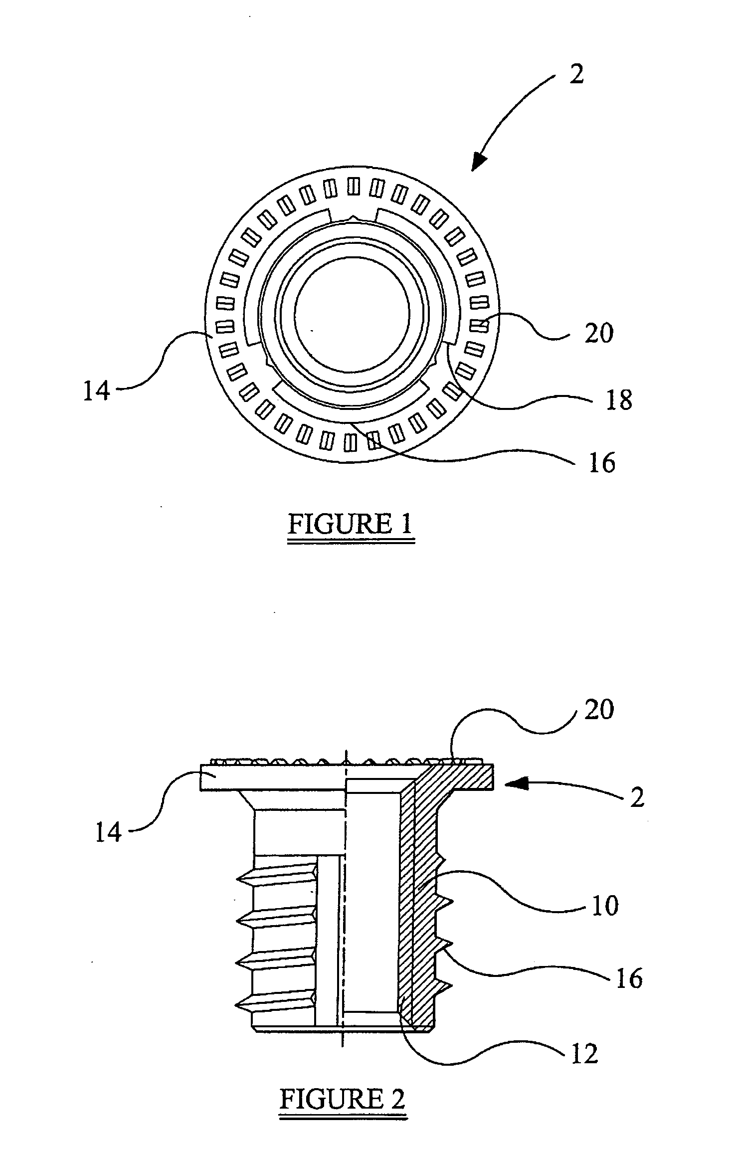
[0011] Preferably, the knurled surface is provided on a radially outwardly extending flange formed at the first end of the fastener.
[0012] Preferably, the knurled surface comprises a radial knurl or a parallel knurl.
[0013] Preferably, the knurled surface partially covers the first end of the fastener.
[0014] Preferably, the knurled surface is formed in a ring on the first end of the fastener.

Problems solved by technology

The threaded insert may fail due to a number of mechanisms.
Also, the threaded insert may fail due to rotation caused by the threaded insert being partially jacked out and compressing the parent material if the material of the parent material is weaker than the material of the threaded insert thereby destroying the joint.
The threaded insert may also fail by rotation where the thread formed by the threaded insert as it is inserted in the parent material becomes stripped and the threaded insert then continues to turn.
This means both that no clamp load can then be created but also that it is very difficult to remove the threaded fastener as the threaded insert simply rotates with the parent material.
While this may prevent partial jacking out, known externally threaded inserts still fail due to rotation, in particular if the bearing surfaces of the threaded insert and the threaded fastener are smooth and near frictionless.

Method used


Image

  • Fastener
  • Fastener
  • Fastener

Examples


Embodiment Construction

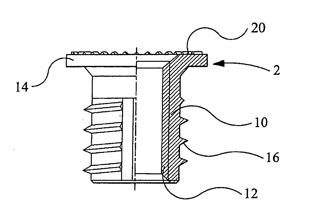
[0023] Referring first to FIGS. 1 and 2 a fastener 2 is shown. The fastener 2 comprises a generally cylindrical body 10 formed with an internal thread 12. In the embodiment illustrated in FIGS. 1 and 2, the fastener 2 comprises a radially outwardly extending flange 14 at a first end. The fastener 2 may be formed from any suitable material, though may usefully be manufactured from brass or steel. The internal thread 12 is adapted to receive a corresponding thread of a threaded fastener (not shown) in a conventional manner.

[0024] In use, the first end of the fastener 2 forms the front bearing face of the fastener 2.

[0025] The body 10 of the fastener 2 is provided with an external thread 16. In the illustrated embodiment, the external thread 16 is formed with a set of three longitudinal flutes 18 equally spaced about the periphery of the body 10. Each of the flutes 18 is formed to have a depth substantially equal to the depth of the external thread 16. Advantageously, the leading edg...


PUM


Abstract

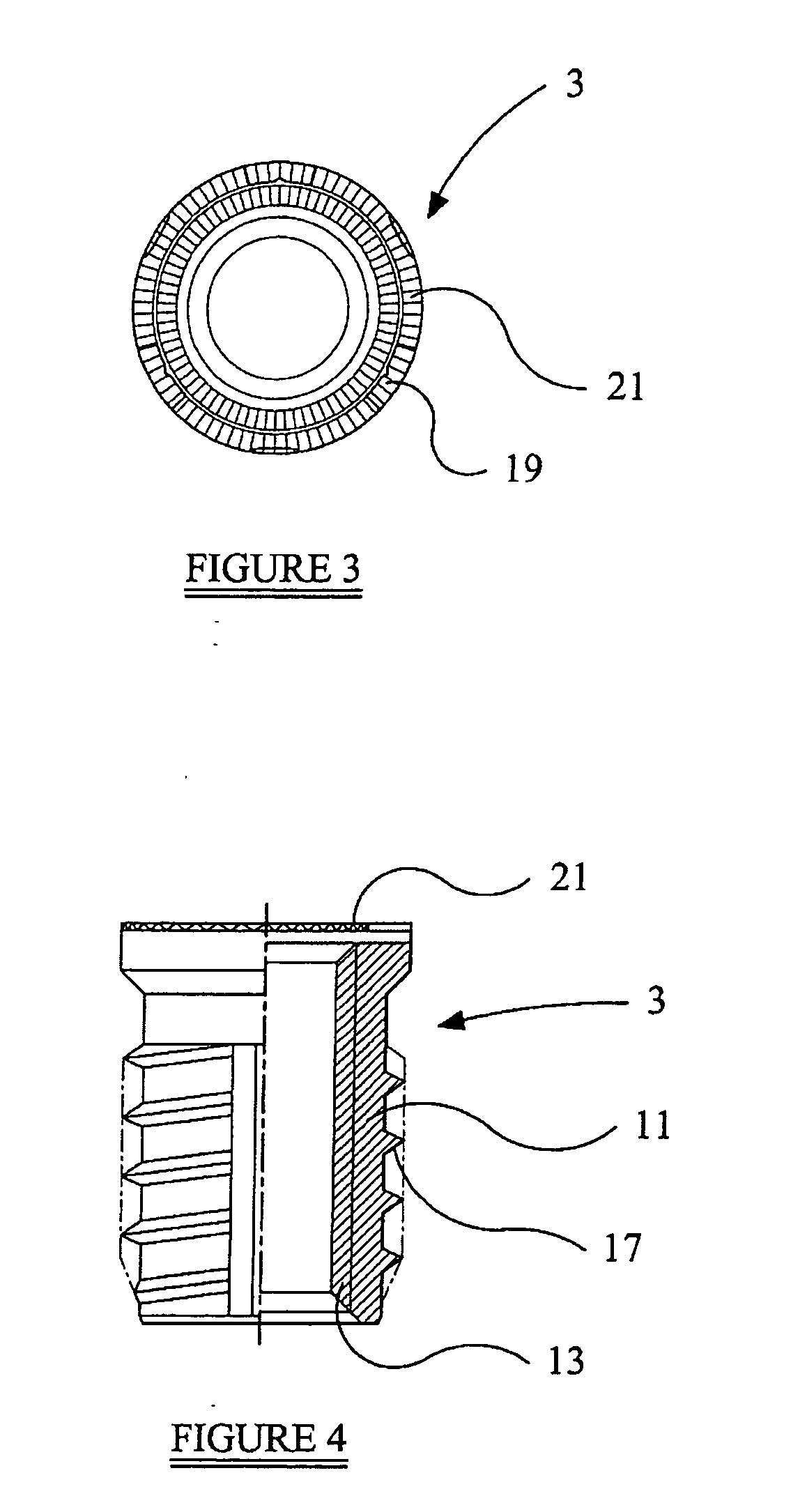
The present invention relates to fasteners and in particular to fasteners, such as threaded inserts, arranged in use to be self-threaded into a parent material of a workpiece. A threaded insert may fail due to a number of mechanisms, including I) due to rotation caused by the threaded insert being partially jacked out and compressing the parent material if the material of the parent material is weaker than the material of the threaded insert thereby destroying the joint or ii) by rotation where the thread formed by the threaded insert as it is inserted in the parent material becomes stripped and the threaded insert then continues to turn. A fastener (2,3) is disclosed comprising a generally cylindrical body (10,11) about which is formed a thread (16,17), the fastener having a first end and a second end, in which a first end of the fastener is provided with a knurled surface (20,21). This has the advantage that an insert having improved torque performance is provided.

Description

FIELD OF THE INVENTION [0001] The present invention relates to fasteners and in particular to fasteners, such as threaded inserts, arranged in use to be self-threaded into a parent material of a workpiece. BACKGROUND TO THE INVENTION [0002] Threaded inserts are used to provide a strong wear resistant thread in a weak material such as a thermoplastic. [0003] It is known to provide inserts with an external knurl form around a shank portion thereof. The knurl form is used for installation of the fastener using heat, ultrasonics or simple press fit. [0004] Other fasteners have an external thread that either cuts or thread forms into the weak material. Such fasteners are known as ‘self tapping’ fasteners and it is to such fasteners that the invention has particular application. [0005] In use, once a threaded insert has been installed in the parent material and a mating component is placed in position, assembly of a threaded fastener, such as a screw or bolt to the threaded insert may com...

Claims


Application Information

Patent Timeline
IPC IPC(8): F16B37/12
CPCF16B37/127
Inventor BARNSDALE, TIMOTHY JOHN RODERICK
Owner TAPPEX THREAD INSERTS
Learn More