Composite torque tube captured end fitting

a composite torque tube and end fitting technology, applied in the direction of shafts, shafts and bearings, shafts for rotary movement, etc., can solve the problems of increasing the length of end fittings, increasing the amount of surface area required in order, and increasing the amount of axial or torque loads, so as to improve the torque and axial the axial loading capability and torque loading capability of the torque tube assembly are enhanced, and the axial loading capacity of the torque tube assembly

Active Publication Date: 2008-09-02
NORTHROP GRUMMAN SYST CORP
View PDF19 Cites 16 Cited by
  • Summary
  • Abstract
  • Description
  • Claims
  • Application Information

AI Technical Summary

Benefits of technology

[0014]The waist section between the forward and aft sections may have a circular cross section which aids in resisting axial loads applied to the end fitting and thereby prevents the end fitting from pulling out of the composite member at the free end. The opposed oval cross sections of the forward and aft sections resists rotation of the end fitting inside the composite member during the application of torque loads on the end fitting. The end fitting may taper radially inwardly to a circular cross section at the end face to provide better axial loading capability to the torque tube assembly.
[0015]The composite member may be comprised of fiber elements embedded in a matrix or resin material. During fabrication of the composite member, such fiber elements are preferably aligned with the predicted load path. More specifically, the fiber elements are preferably placed in mechanical tension loading (i.e., pulling the fibers) as torque loads are applied to the end fitting. By dividing the composite member into two sections near the end fitting, axial loading capability as well as torque loading capability of the torque tube assembly is enhanced by angular offset between the aft section lobes in relation to the forward section lobes. Torque and axial loading capability of the torque tube assembly may be improved by providing a layer of adhesive between the inner surface of the forward and aft sections and the outer surface of the end fitting.
[0016]The angular offset of cross-sectional shapes of the forward and aft section provides a mechanical advantage which better resists torque loading between the composite member and the end fitting. The mechanical advantage results from the composite member resisting rotation due to the lobes in the end fitting. The composite member may be fabricated from any fiber matrix material including graphite material, fiberglass material and Kevlar material. The end fitting may be formed of any material but is preferably a metallic material such as aluminum.

Problems solved by technology

Unfortunately, the greater the amount of axial or torque loads that is applied to the torque tube, the larger the amount of surface area that is required in order to accommodate such higher loads.
As a result, applications of extremely high axial or torque loads necessitate the use of end fittings that extend along a large portion of the composite member.
Unfortunately, the end fittings are increased in length merely for the purpose of increasing the amount of available adhesive bond area between the end fitting and the composite member.
Such extreme lengths of the end fittings inside the composite member negates any benefit gained through the use of the lightweight composite materials in torque tube assemblies.
The resulting structure may be more time-consume and costly to manufacture that a metallic version constructed in accordance with prior art design practices.
However, as is well known in the art of composite construction, forming a hole in a composite structure oftentimes results in severing one or more of the load carrying fibers within the composite tube.
Furthermore, the act of forming a hole in the composite member is sometimes expensive and time consuming due to the need for specialized drilling equipment to prevent breaking or severing the resin and fiber elements around the hole.
Finally, the addition of a pin or fastener to aid in transmitting a portion of the torque from the end fitting to the tube member is not an optimized lightweight solution.
However, the need to form special surface features such as serrations on the outer surface of the end fitting presents additional machining challenges and increases fabrication costs.
Furthermore, the serrations and surface features themselves may sever reinforcing fibers embedded within the resin matrix of the composite tube member thereby increasing the risk of a failure in the transmission of high torsional loads.

Method used


Image

  • Composite torque tube captured end fitting
  • Composite torque tube captured end fitting
  • Composite torque tube captured end fitting

Examples


Embodiment Construction

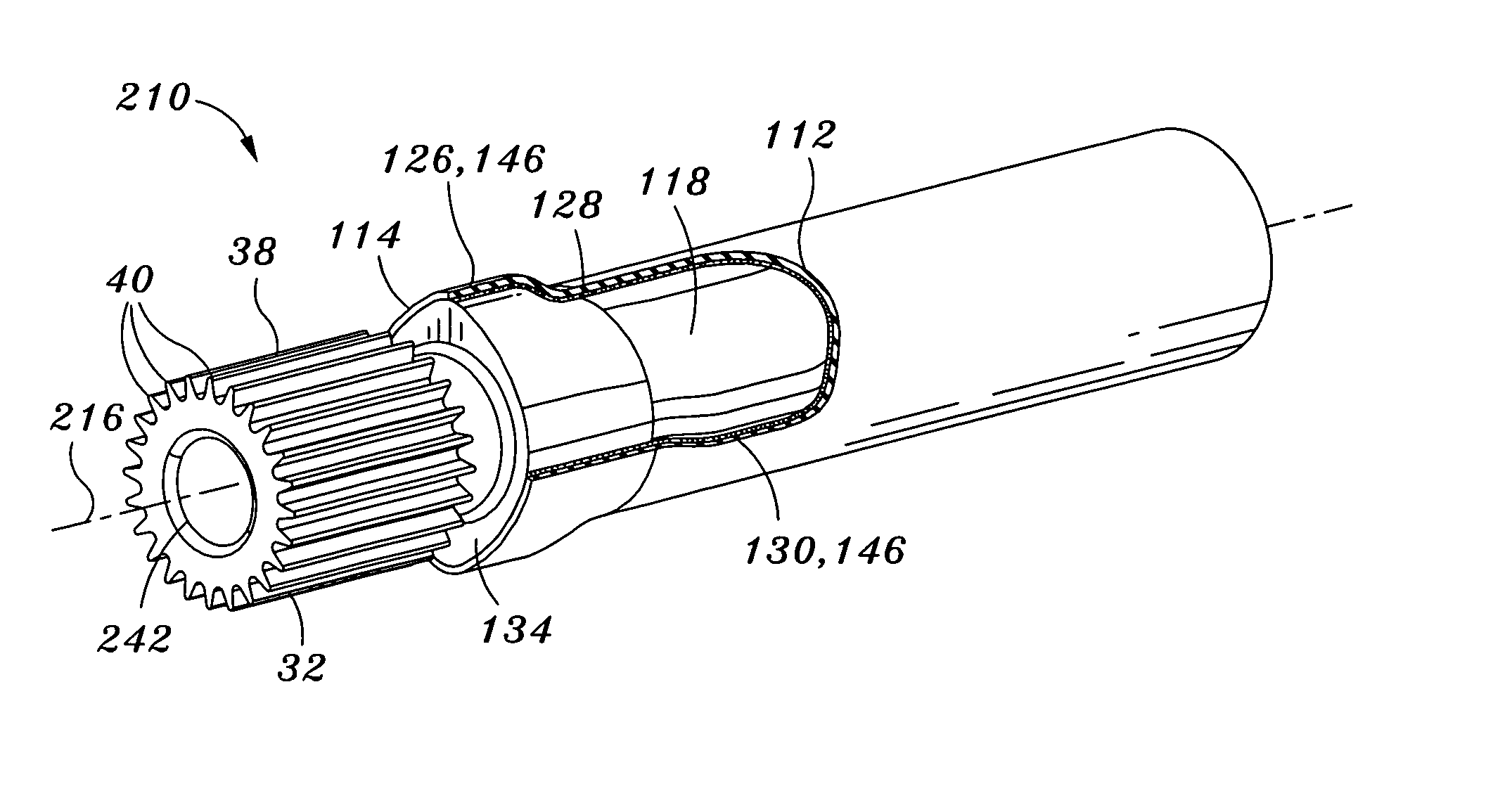
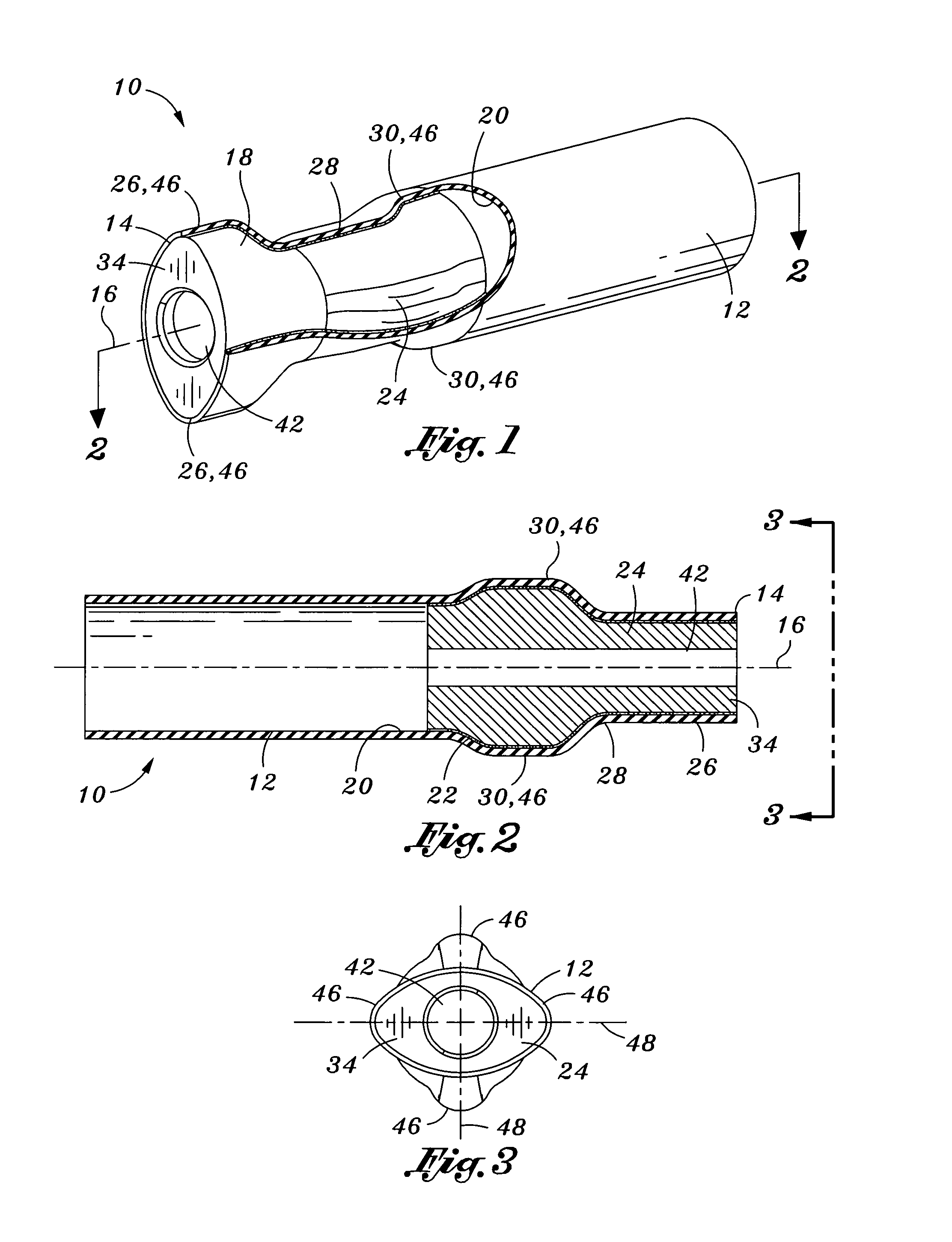
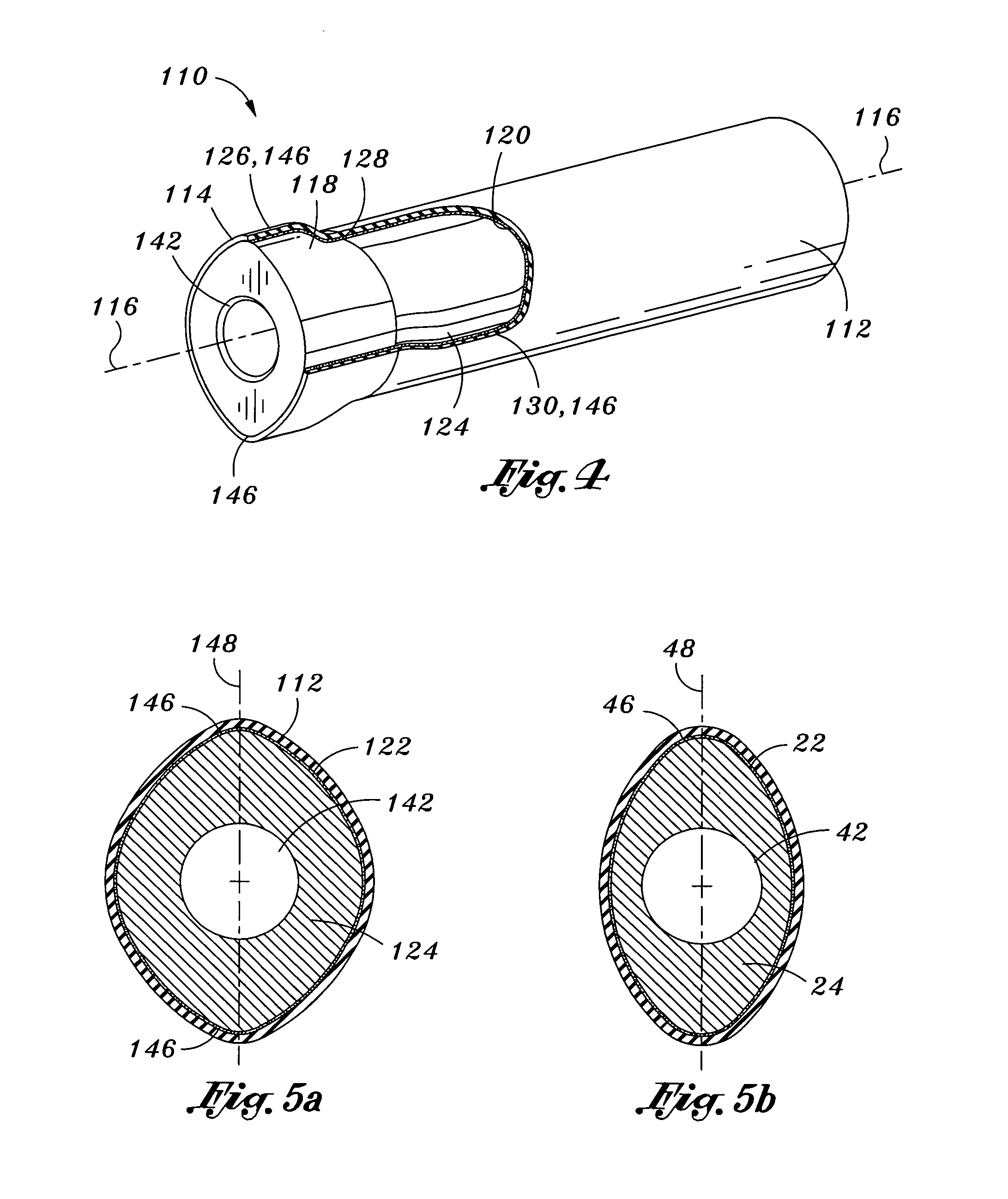
[0028]Referring now to the drawings wherein the showings are for purposes of illustrating the present invention and not for purposes of limiting the same, provided is a torque tube assembly 10 which, as shown in FIGS. 1-3, comprises a hollow composite member 12 having at least one end portion with an end fitting 24 inserted thereinto. More specifically, the end fitting 24 is formed with a shaped that complementary to the composite member 12 and is at least partially enclosed or encased by forward and aft sections 26, 30 of the hollow composite member 12.

[0029]The hollow composite member 12 may be defined as a generally elongate tubular member having a tube axis 16, an inner surface 20 and an outer surface 18. The composite member 12 includes at least one free end 14 into which the end fittings 24 may be inserted. As shown in FIGS. 1-3, the free end 14 of the hollow composite members 12 is also divided into forward and aft sections 26, 30 with a waist section 28 being disposed betwee...


PUM


Abstract

A torque tube assembly includes a hollow composite member and an end fitting. The composite member has at least one end portion divided into a forward section and an aft section. The forward section is disposed adjacent a free end of the composite member. Each one of the forward and aft sections has at least one lobe extending radially outwardly along a lobe axis. The lobe axis of the forward section is preferably angularly offset from the lobe axis of the aft section. The end fitting is formed complementary to the composite member and is at least partially enclosed by the forward and aft sections.

Description

CROSS-REFERENCE TO RELATED APPLICATIONS[0001]Not ApplicableSTATEMENT RE: FEDERALLY SPONSORED RESEARCH / DEVELOPMENT[0002]Not ApplicableBACKGROUND OF THE INVENTION[0003]The following invention relates to composite structures and, more particularly, to a uniquely configured composite torque tube end fitting design that is specifically adapted to provide increased resistance to axial and torque loads.[0004]The prior art includes many structural configurations wherein torque from one member is transferred to another member. For example, an automobile driveshaft is configured to transmit torque between an engine and driving wheels. Similarly, driveshafts may be incorporated into various types of aircraft and seagoing ships. Driveshafts are generally comprised of elongate rod or tubing having end fittings specifically configured to be connected to transmission devices.[0005]With an increasing demand for more efficient structures, there has been a trend away from metallic structures in favor...

Claims


Application Information

Patent Timeline
Patent Type & Authority Patents(United States)
IPC IPC(8): F16C1/02
CPCF16C3/023
Inventor BORGES, JOHN S.TREVISANUT, VAIL R.SCARR, DAVID R.
Owner NORTHROP GRUMMAN SYST CORP
Why Eureka
Try Eureka