Novel high torque density high power factor fault tolerant permanent magnet vernier machine and its modulation method

A technology of power factor and vernier motors, applied in synchronous motors with stationary armatures and rotating magnets, motor generator control, electronic commutation motor control, etc., can solve the problem of low winding factor, inappropriateness, and low magnetic field utilization And other issues

Active Publication Date: 2016-09-21
JIANGSU UNIV
4 Cites 12 Cited by

AI-Extracted Technical Summary

Problems solved by technology

[0005] In the existing technology, the permanent magnet vernier motor generally adopts three-phase fractional slot double-layer concentrated winding, and the number of slots per pole and phase is q=1/2. This winding scheme will make the winding factor low and the magnetic field utilization rate also low , and the phase-to-phase coupling degree is high, such a motor has poor fault-tolerant performance, or even has no fault-tolerant ...

Method used

5 numbers of described surface-embedded permanent magnets are identical with the number of poles of armature winding; Described surface-embedded permanent magnet 5 has nine pieces, and armature winding is nine pairs of poles and concentrates on the armature teeth, A five-phase winding is used to increase the power of the motor and the fault-tolerant effect of the motor.
Motor structure comprises coaxial stator, inner rotor and outer rotor, and inner rotor permanent magnet selects radial arrangement mode, and permanent magnet magnetization direction is tangential and N pole and S pole are alternately arranged; Outer rotor permanent magnet adopts Surface-embedded, the magnetization direction of the permanent magnet points to the center of the circle; 10 thinner fault-tolerant teeth and 10 thicker armature teeth are alternately arranged on the stator; each fault-tolerant tooth and the top of the armature teeth have virtual slots , forming two virtual teeth; the armature winding adopts a single-layer concentrated winding method. The present invention utilizes the combination of the vernier motor, the magnetic gear and the fault-tolerant performance, further increases the torque output capacity of the motor on the basis of the vernier motor, and achieves a more efficient utilization of the motor; the motor has fault-tolerant performance to ensure the reliable operation of the motor; at the same time, the structure It has a magnetic gear structure, which can greatly improve the power factor of the motor. Using the invention can simplify the difficulty of control, increase the reliability of motor operation, and has great application prospects.
The difference between the present invention and prior art: the present invention has carried out innovative change on the basis of prior art, and existing fault-tolerant permanent magnet vernier motor has high torque density, the advantage that fault-tolerant performance is good, but Its power factor is low; the present invention changes the conventional surface-mounted rotor structure, adopts tangentially excited radial permanent magnets, and adds a rotor on the outer layer to form a magnetic gear structure with the radial rotor. The modulation teeth of the inner stator have two functions, one is the modulation of the vernier motor structure, that is, the modulation of the magnetic field of the inner stator and the inner rotor; the other is the modulation of the magnetic gear, that is, the magnetic field modulation of the inner rotor and the outer rotor. This structure makes full use of the internal spa...

Abstract

The invention discloses a novel high torque density high power factor fault tolerant permanent magnet vernier machine and its modulation method. The vernier machine structure comprises a coaxial stator, an inner rotor and an outer rotor, wherein the permanent magnets of the inner rotor are distributed in a radial arrangement with their magnetization directions being tangential and their N poles and the S poles arranged in alternation. The permanent magnets of the outer rotor are arranged in a face embedding manner with their magnetization directions pointing to the center of circle. Ten smaller fault-tolerant teeth and ten bigger armature teeth are alternately arranged on the stator. The tops of each fault-tolerant tooth and the armature tooth are provided with a virtual slot, forming two virtual teeth. The armature windings adopt a single-layer concentrated winding manner in their winding. The invention utilizes the combination of a vernier machine, a magnetic gear and a fault-tolerant performance to further increase the motor torque outputting capacity on the basis of the vernier machine to achieve a more efficient utilization of the motor. This motor, with fault-tolerant performance, is ensured to provide reliable operations. Structured with a magnetic gear, the vernier machine can greatly enhance the motor power factor. The invention can increase the reliability of the motor operation and has great application prospects.

Application Domain

Electronic commutation motor controlMagnetic circuit rotating parts +7

Technology Topic

High torquePower factor +7

Image

  • Novel high torque density high power factor fault tolerant permanent magnet vernier machine and its modulation method
  • Novel high torque density high power factor fault tolerant permanent magnet vernier machine and its modulation method
  • Novel high torque density high power factor fault tolerant permanent magnet vernier machine and its modulation method

Examples

  • Experimental program(1)

Example Embodiment

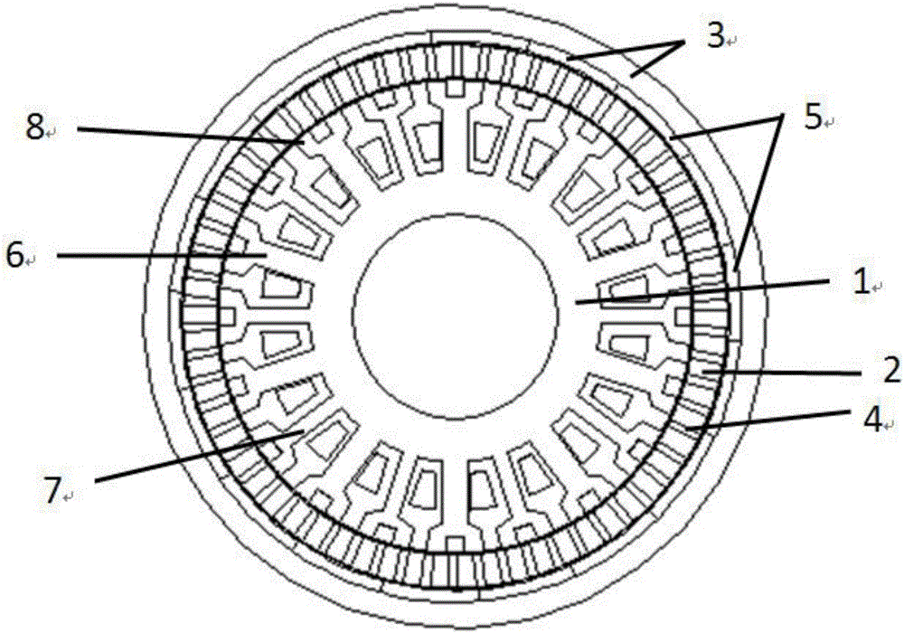
[0042] A new type of high torque density and high power factor fault-tolerant permanent magnet vernier motor of the present invention includes an inner stator 1, an inner rotor 2 and an outer rotor 3 from the inside to the outside, between the inner stator 1 and the inner rotor 2, and the inner rotor 2 and the outer rotor 3 are both left with an air gap; the inner rotor 2 is embedded with radial permanent magnets 4, using tangential excitation, the N poles and S poles of the radial permanent magnets 4 are alternately arranged along the circumference; the inner rotor 2 A number of surface-embedded permanent magnets 5 are embedded between the outer rotor 3 and the outer rotor 3. The surface-embedded permanent magnets 5 are unipolar, and they are all excited in the direction of the center of the circle; the inner stator 1 is alternately arranged with armature teeth 6 and fault-tolerant tooth 7; the armature tooth 6 and the fault-tolerant tooth 7 are evenly arranged with equal-sized modulation teeth 8; the armature tooth adopts a concentrated winding method around the multi-pole armature winding; inner rotor 2, outer rotor 3 and modulating teeth 8 form a magnetic gear structure; inner stator 1 and inner rotor 2 form a vernier motor structure; inner stator 1 and outer rotor 3 form a conventional motor structure.
[0043] The ratio of the radian of the surface-embedded permanent magnet 5 to the radian of the radial permanent magnet 4 is between 7.8 and 8.8. The preferred embodiment of the present invention is 8.4, which achieves a higher torque density when the amount of permanent magnets is small. aims.
[0044] The number of pole pairs of the armature winding P a , The number of inner rotor pole pairs P i , The number of outer rotor pole pairs P o And modulating tooth number n s Meet the following relationship: P a =P o , N s =P a +P i.
[0045] The number of 5 surface-embedded permanent magnets is the same as the number of pole pairs of armature windings; there are 9 surface-embedded permanent magnets 5, and the armature windings are wound on the teeth of the armature in nine pairs of poles, using five-phase Winding to increase the power of the motor and the fault tolerance of the motor.
[0046] The rotation speed of the outer rotor 3 ω o , The inner rotor speed ω i Satisfy the relationship: No winding is wound on the fault-tolerant tooth 7, and each phase winding is physically isolated.
[0047] Reference figure 1 The present invention includes an inner stator 1, an inner rotor 2 and an outer rotor 3. The inner stator 1 and the inner rotor 2 are embedded with radial permanent magnets of rubidium-iron-boron material 4, which adopt tangential excitation, with N-pole and S-pole edges. Alternately arranged along the circumference; between the inner rotor 2 and the outer rotor 3, there are 9 embedded permanent magnets 5 embedded in the surface, the surface embedded permanent magnets 5 are excited in the direction of the center of the circle; the inner stator is alternately arranged with armature teeth 6 And fault-tolerant teeth 7.
[0048] The present invention adopts five-phase armature winding, which is a fractional slot concentrated winding with the number of slots per phase per pole q<1/2. The winding is wound on 10 armature teeth 6, and its distribution appears as ADBECADBEC, forming 9 pairs of poles. Armature magnetic field. The armature teeth 6 and the fault-tolerant teeth 7 are evenly arranged with 40 modulating teeth 8 of equal size, see figure 2. According to the relationship between the number of pole pairs of the vernier motor and the modulation tooth: P i = N s ±P a , Get P i = 31 or P i =49, take P i =31. At the same time, in order to satisfy the effect that the outer rotor and the inner rotor form a magnetic gear, it is easy to find that the number of 5 pole pairs of the outer rotor surface embedded permanent magnet is equal to 9.
[0049] When the armature winding is energized with alternating current, the 9 pairs of magnetic field harmonics generated by it are modulated by the modulation teeth, and 31 pairs of magnetic field harmonics are formed in the air gap to interact with the inner rotor to generate torque; at the same time, the armature winding The 9 pairs of pole harmonics will also act on the outer rotor through the inner rotor and the air gap, generating torque on the outer rotor.
[0050] The specific modulation process of the present invention is described as follows: With P a The magnetic field generated by the armature winding of the opposite pole is at a speed Ω s When rotating, after the magnetic field is modulated by the modulation pole 8, a spatially distributed magnetic field is formed in the air gap. The radial component B of the magnetic induction intensity at the radius of r and the spatial angle of θ is formed. r Can be expressed as:
[0051] B r ( r , θ ) = B r 0 ( r , θ ) · λ r ( r , θ ) = λ r 0 ( r ) X m = 1 , 3 , 5 , ... b r m ( r ) cos ( m p ( θ - Ω r t ) + mpθ 0 ) + 1 2 X m = 1 , 3 , 5 , ... X j = 1 , 2 , 3 , ... λ r j ( r ) b r m cos ( ( m p + jn s ) ( θ - ( mpΩ r + jn s Ω s ) ( m p + jn s ) t ) + mpθ 0 ) + 1 2 X m = 1 , 3 , 5 , ... X j = 1 , 2 , 3 , ... λ r j ( r ) b r m cos ( ( m p - jn s ) ( θ - ( mpΩ r - jn s Ω s ) ( m p - jn s ) t ) + mpθ 0 )
[0052] Where: b rm Is the Fourier coefficient of the radial magnetic density distribution, λrj is the Fourier coefficient of the radial modulation function; t is the time change θ 0
[0053] p m, k =|mp+kn s |
[0054] m=1, 3, 5...∞
[0055] k=0, ±1, ±2, ±3,...±∞
[0056] The rotational angular velocity of the magnetic density space harmonic can also be calculated as:
[0057] Ω m , k = m p m p + kn s Ω r + kn s m p + kn s Ω s
[0058] The modulation ratio of the motor is:
[0059] G r = n s - P a P a = P i P a
[0060] image 3 Is the distribution diagram of the air gap magnetic density of the no-load outer layer of the present invention, Figure 4 It is the Fourier decomposition diagram of the no-load outer air gap magnetic density distribution of the present invention. It can be seen that the permanent magnet will generate 9 pairs of poles and 31 pairs of pole magnetic fields in the outer air gap. Among them, 9 pairs of poles interact with the outer rotor. The interaction between the opposite pole and the outer rotor shows that this structure has the characteristics of a magnetic gear.
[0061] Figure 5 Is the air gap magnetic density distribution diagram of the unloaded inner layer of the present invention, Image 6 It is the Fourier decomposition diagram of the magnetic density distribution of the no-load inner air gap of the present invention. It can be seen from the figure that there are 9 pairs of poles and 31 pairs of magnetic fields in the inner air gap, while the inner air gap is only connected to the inner rotor and the inner stator. The number of pole pairs of the inner rotor permanent magnet is 31, and there are 9 pairs of poles in the air gap. The magnetic field is formed by the inner rotor magnetic field modulated by the modulating teeth. This shows that the inner rotor and the inner stator form a vernier motor structure.
[0062] Figure 7 It is the no-load back EMF diagram of the motor of the present invention, and the back EMF is an important parameter that reflects the performance of the motor. It can be seen from the figure that the back-EMF distortion is not very large, indicating that the design of the motor is relatively reasonable.
[0063] Figure 8 Is the waveform diagram of the loading voltage and loading current of the present invention, i d The control strategy of =0 is to apply the load current of the same phase through the back EMF. The phase angle of the loaded voltage and the loaded current is called the power factor angle, and the cosine function is calculated to obtain the motor power factor. From the figure, it can be seen that the motor load voltage The phase difference with the loading current is small, so the power factor of the present invention will be relatively large.
[0064] The mechanism of the present invention for generating high torque: 1. Due to the presence of the modulation teeth, the rotation speed of the inner stator armature magnetic field and the outer rotor permanent magnet magnetic field produces a rotation speed ratio of 31/9, so that the rotor rotates at a very small angle. The angle that the distribution of magnetic lines of force changes greatly can be understood as the rotor rotates 9° and the spatial distribution of magnetic lines of force rotates 31°. Obviously, the cutting speed of the magnetic line of force can still be fast at low speeds, thus increasing the output torque; 2. Outer rotor and The inner stator forms a conventional motor, and the outer rotor and the inner rotor form a magnetic gear structure. Therefore, the torque generated by the armature winding on the outer rotor will be amplified by the magnetic gear and applied to the inner rotor with a lower speed. The output torque has been further improved.
[0065] The mechanism of the present invention to produce high power factor: For the vernier motor, the modulation ratio G r The larger the value, the stronger the output torque capacity of the motor; but as G r Becomes larger, the number of permanent magnet pole pairs and the number of modulation teeth of the motor will also increase accordingly, which will increase the leakage of the motor, that is, the equivalent inductance value of the motor L s Increased, resulting in a low power factor of the vernier motor, and its power factor is generally below 0.5. The present invention adds a rotor to the outer layer of the vernier motor, and a radially excited permanent magnet is marked on the rotor. The magnetic field lines of the permanent magnet will guide the leakage magnetic field lines of the vernier motor inside, so that the internal magnetic field of the motor can be fully utilized. This improves the power factor of the motor.
[0066] The difference between the present invention and the prior art: the present invention has made innovative changes on the basis of the prior art. The existing fault-tolerant permanent magnet vernier motor has the advantages of high torque density and good fault tolerance, but its power factor On the low side; the present invention changes the conventional surface-mounted rotor structure, adopts tangential excitation radial permanent magnets, and adds a rotor to the outer layer to form a magnetic gear structure with the radial rotor, so that the inner stator The modulation tooth has two functions. One is the modulation of the vernier motor structure, that is, the modulation of the magnetic field of the inner stator and the inner rotor; the second is the modulation of the magnetic gear, that is, the modulation of the magnetic field of the inner and outer rotors. This structure makes full use of the internal space of the motor and further improves the torque capacity on the basis of the prior art. In addition, the outer rotor permanent magnet of the present invention uses unipolar permanent magnets, which greatly reduces the amount of permanent magnets and at the same time ensures that the motor has a larger torque density. Since the magnetic gear structure itself has the advantage of high power factor, the present invention incorporates this structure, and the power factor is greatly improved on the basis of the improvement of torque capacity, which can reach more than 0.9. Therefore, the present invention has a good Application prospects.
[0067] The motor structure includes a coaxial stator, an inner rotor and an outer rotor. The permanent magnets of the inner rotor are arranged radially. The magnetizing direction of the permanent magnets is tangential and the N and S poles are alternately arranged. The permanent magnets of the outer rotor are embedded in the surface. , The magnetizing direction of the permanent magnets are pointing to the center of the circle; 10 thinner fault-tolerant teeth and 10 thicker armature teeth are alternately arranged on the stator; each fault-tolerant tooth and the top of the armature tooth are opened with a virtual slot, forming two A virtual tooth; the armature winding adopts a single-layer concentrated winding method. The invention utilizes the combination of vernier motor, magnetic gear and fault-tolerant performance to further increase the torque output capacity of the motor on the basis of the vernier motor to achieve more efficient use of the motor; this motor has fault-tolerant performance to ensure the reliable operation of the motor; With a magnetic gear structure, it can greatly improve the power factor of the motor. The use of the invention can simplify the control difficulty, increase the reliability of the motor operation, and has a larger application prospect.
[0068] In the description of this specification, descriptions with reference to the terms "one embodiment", "some embodiments", "exemplary embodiments", "examples", "specific examples", or "some examples" etc. mean to incorporate the implementation The specific features, structures, materials or characteristics described by the examples or examples are included in at least one embodiment or example of the present invention. In this specification, the schematic representations of the above terms do not necessarily refer to the same embodiment or example. Moreover, the described specific features, structures, materials or characteristics may be combined in any one or more embodiments or examples in a suitable manner.
[0069] Although the embodiments of the present invention have been shown and described, those of ordinary skill in the art can understand that various changes, modifications, substitutions, and modifications can be made to these embodiments without departing from the principle and purpose of the present invention. The scope of the present invention is defined by the claims and their equivalents.

PUM

no PUM

Description & Claims & Application Information

We can also present the details of the Description, Claims and Application information to help users get a comprehensive understanding of the technical details of the patent, such as background art, summary of invention, brief description of drawings, description of embodiments, and other original content. On the other hand, users can also determine the specific scope of protection of the technology through the list of claims; as well as understand the changes in the life cycle of the technology with the presentation of the patent timeline. Login to view more.
Why Eureka
Try Eureka