Efficient three-phase slot-free permanent magnet motor

A permanent magnet motor, high-efficiency technology, applied to synchronous motors with stationary armatures and rotating magnets, electrical components, electromechanical devices, etc., can solve the problems of low winding factor, low power density, large loss, etc., and achieve improved Effects of winding factor, reduction of torque ripple, and improvement of positioning accuracy

Active Publication Date: 2012-07-11
HARBIN INST OF TECH
View PDF0 Cites 0 Cited by
  • Summary
  • Abstract
  • Description
  • Claims
  • Application Information

AI Technical Summary

Problems solved by technology

[0004] In order to solve the shortcomings of existing slotless motors, such as low winding factor, low power density, large loss and high temperature rise, the present invention proposes a high-efficiency three-phase slotless permanent magnet motor

Method used


Image

  • Efficient three-phase slot-free permanent magnet motor
  • Efficient three-phase slot-free permanent magnet motor
  • Efficient three-phase slot-free permanent magnet motor

Examples


specific Embodiment approach 1

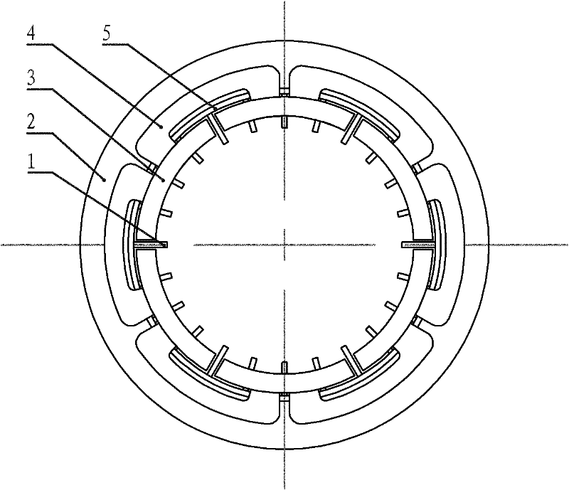
[0010] Embodiment 1: A kind of high-efficiency three-phase slotless permanent magnet motor described in this embodiment is a cylindrical rotating electrical machine, which is composed of an armature, a rotor and an air gap; the armature is composed of an armature core 2, a winding and Composed of a coil frame, the armature core 2 is circular, the coil frame is composed of a thin-walled tube 5 and 6p thin partitions 1, p is the number of pole pairs of the permanent magnet of the motor rotor, p≥2, the thin-walled tube 5 is coaxial with the armature core 2 and is fixed on the side of the armature core 2 close to the rotor. The thin partitions 1 are elongated, and each thin partition 1 is radial with the axis of the armature core 2 as the axis of symmetry. Evenly distributed and fixed on the side wall of the thin-walled cylinder 5 near the rotor side, and the planes where all the thin-walled partitions 1 are located intersect with the axis of the armature core 2, and the two adjace...

specific Embodiment approach 2

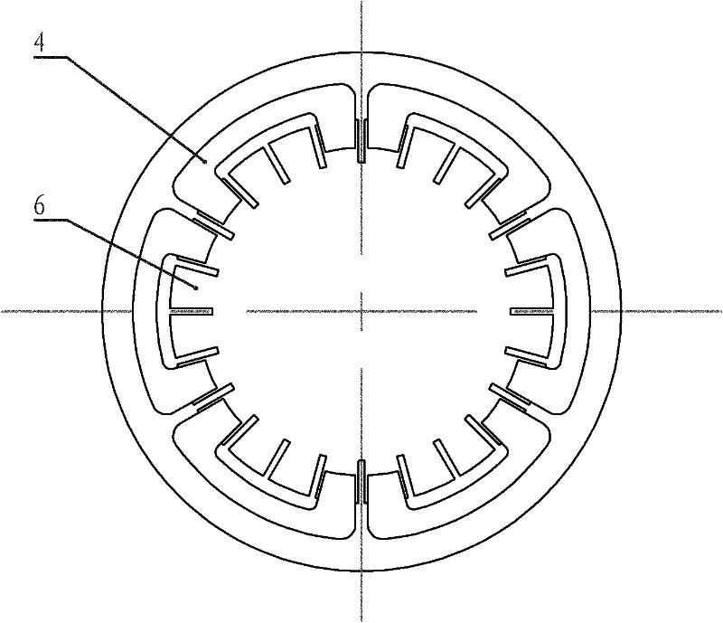
[0013] Embodiment 2: This embodiment is a further limitation of the high-efficiency three-phase slotless permanent magnet motor described in Embodiment 1. In this embodiment, a plurality of skeletons are evenly distributed in the axial direction on the side of the stator core adjacent to the rotor. The positioning groove, the positioning rib is embedded in the positioning groove, so that the coil skeleton is fixed between the positioning rib and the skeleton positioning groove.

[0014] In this embodiment, a device for fixing the coil frame is added, so that the coil frame can be stably fixed on the stator core.

specific Embodiment approach 3

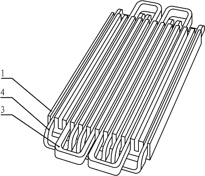
[0015] Specific Embodiment Three: A high-efficiency three-phase slotless permanent magnet linear motor described in this embodiment is a flat motor, which consists of a primary, a secondary, and an air gap; the secondary of the motor is a bilateral structure, and each side of the secondary It is composed of a yoke plate and a permanent magnet. The primary is located between two secondary plates. The primary includes a coil, a coil frame and a primary output plate; the coil frame is composed of a thin plate and several thin partitions. The thin plate is parallel to the secondary, thin The baffles are strip-shaped, and each thin baffle is perpendicular to the thin plate at equal intervals along the moving direction of the mover and fixed on the thin plate. A line groove is formed between two adjacent thin baffles. The slot pitch is equal to the secondary pole pitch, and all coils have the same shape, consisting of two straight sides and two ends, both of which are bent towards on...


PUM


Abstract

The invention provides an efficient three-phase slot-free permanent magnet motor, belonging to the field of a motor, which solves the shortcomings of low winding factor, low power density, high loss and high temperature rise of the existing slot-free motor. When the motor is a cylinder type rotary motor, an armature iron core is circular; a coil framework fixed at the side of the armature iron core close to the rotor is formed by a thin-wall cylinder and thin clapboards; a plurality of thin clapboards are evenly and fixedly distributed in the thin-wall cylinder in a radial pattern by taking the axis of the armature iron core as a symmetrical axis; a wiring slot is formed between two adjacent thin clapboards; the pitch of each coil in the winding is the distance between the adjacent four thin clapboards in the coil framework; half of end portion bending coils in 3p coils are orderly and adjacently embedded in the wiring slot formed by the thin clapboards; and the two ends both bend towards the stator iron core side; and the other coils are orderly and adjacently embedded in the wiring slot formed by the other thin clapboards, wherein effective sections of the adjacent coils in the adjacent two flat coils are positioned in two effective sections of the same end portion bending coil.

Description

technical field [0001] The invention relates to a high-efficiency three-phase slotless permanent magnet motor, which belongs to the field of motors. Background technique [0002] The permanent magnet brushless motor with slotless structure integrates permanent magnet, brushless and slotless, which fundamentally solves the problem of low output, large torque fluctuation, large hysteresis and eddy current loss, magnetic saturation, Noisy, low efficiency and slow response problems. Through the use of permanent magnet excitation, the excitation coil on the rotor is eliminated, which is highly efficient and energy-saving; the brushless structure realizes no brush, no commutator, no spark, and high power-to-weight ratio; the slotless structure has a large space for winding distribution and heat dissipation Good, the armature copper loss is small, the iron core is not saturated, the iron loss (eddy current, hysteresis loss) is small, the cogging effect is eliminated, the cogging t...

Claims


Application Information

Patent Timeline
Patent Type & Authority Patents(China)
IPC IPC(8): H02K21/14H02K41/03H02K3/24
Inventor 寇宝泉曹海川赵斌超张达
Owner HARBIN INST OF TECH
Why Eureka
Try Eureka