

Method and apparatus for resolving coloring conflicts between phase shifters
a phase shifter and conflict resolution technology, applied in photomechanical treatment, instruments, computing, etc., can solve the problems of circuit designers having to deal with problems, coloring conflicts, and the feature size of these circuit elements continues to decreas
Inactive Publication Date: 2004-02-24
SYNOPSYS INC
View PDF90 Cites 42 Cited by
- Summary
- Abstract
- Description
- Claims
- Application Information
AI Technical Summary
Problems solved by technology
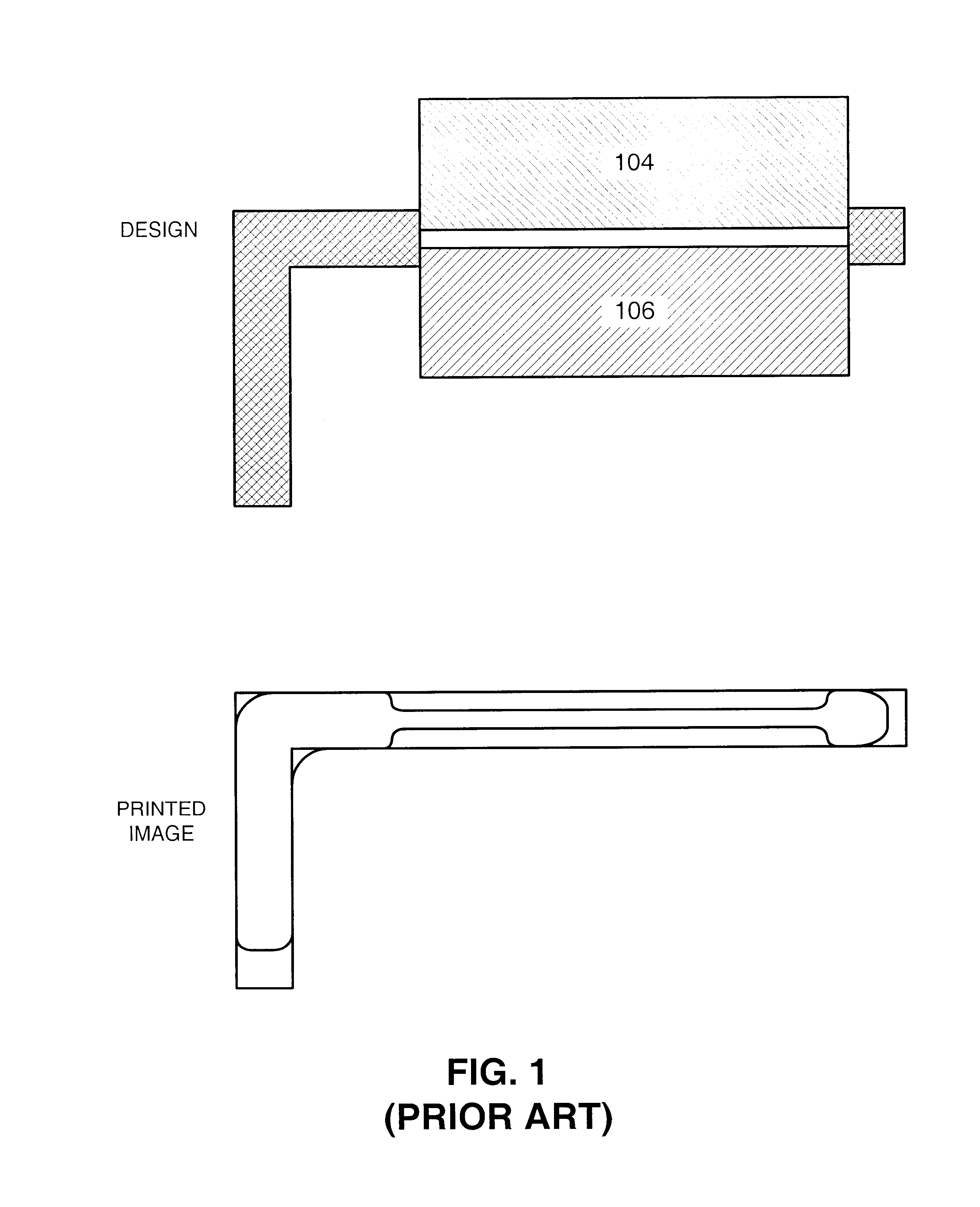
As the feature size of these circuit elements continues to decrease, circuit designers are forced to deal with problems that arise as a consequence of the optical lithography process that is typically used to manufacture integrated circuits.
During phase shifting, destructive interference caused by two adjacent clear areas on a mask is used to create an unexposed area on the photoresist layer.
Coloring conflicts arise when nearby phase shifting regions have the same phase.
This can cause unwanted exposure of the photoresist layer.
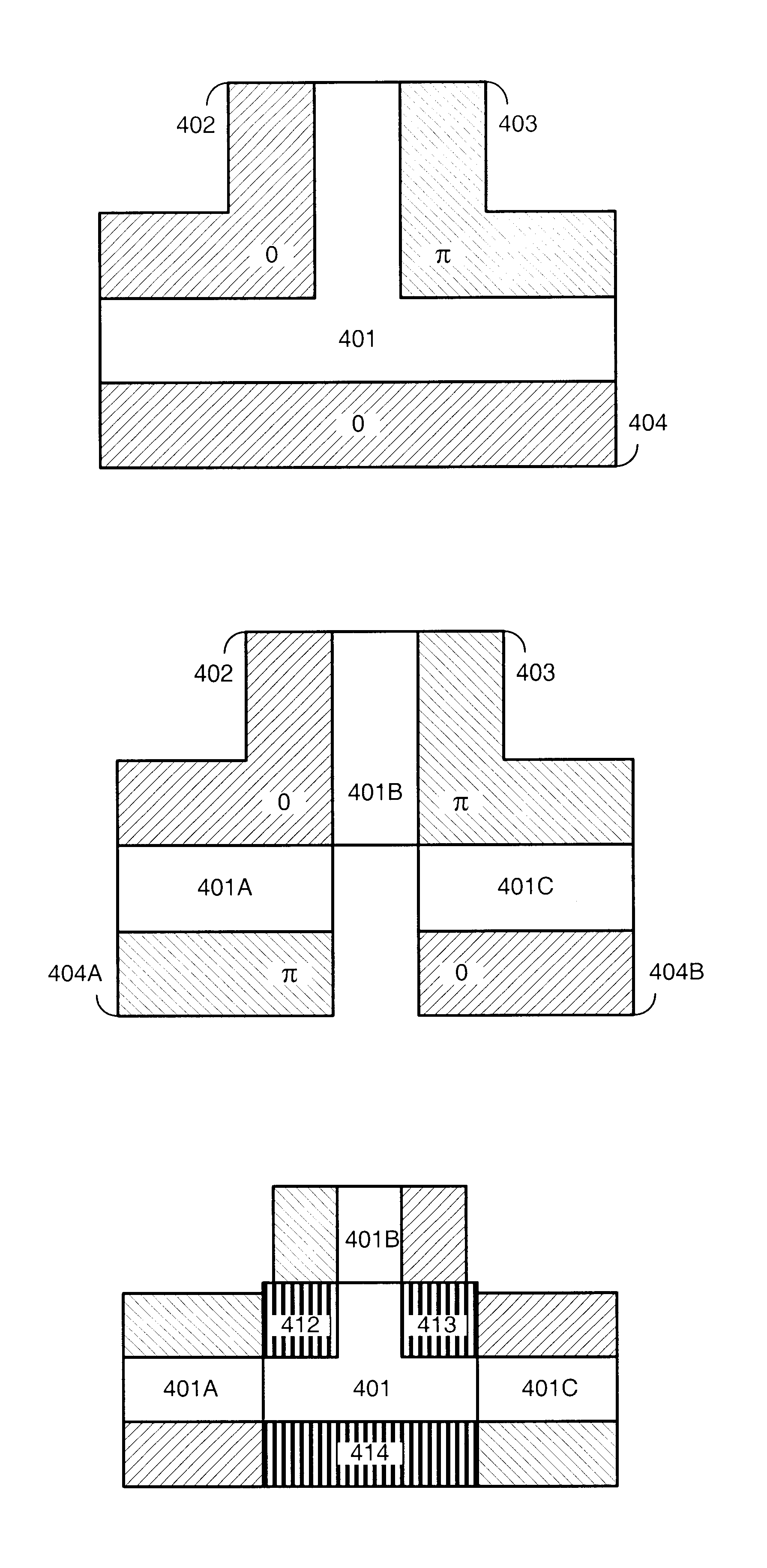
A particular problem arises in defining phase shifters to form junctions, such as T-junctions and L-junctions and assigning phase to the same.
As was described above with reference to FIG. 4A, a particular problem arises in producing phase shifters to form junctions, such as T-junctions and L-junctions.
However, note that all possible assignments of phases to the phase shifters 402-404 cause coloring violations.
In some embodiments, an error results and / or the process is stopped if the hard coloring requirements cannot be met.
Method used
View moreImage
Smart ImageViewing Examples

Examples
example 908
is a T-junction in close proximity to a polysilicon line 909. In this example, if region III is removed, a corresponding region IV must be removed on the other side of polysilicon line 909 in order to prevent a coloring conflict.
example 914
presents an L-junction with two different regions I and II that can be cut away to obviate coloring conflicts. Note that regions I and II correspond to regions 416 and 415, respectively, in FIG. 4D.
examples 916 and 92
0 are similar to the L-junction illustrated in example 914, so they are treated in the same way with corresponding regions I and II that can be cut away.
Login to View More PUM
| Property | Measurement | Unit |
|---|---|---|
| critical-dimension | aaaaa | aaaaa |
| phase shifting | aaaaa | aaaaa |
| phase | aaaaa | aaaaa |
Abstract
One embodiment of the invention provides a system that automatically resolves conflicts between phase shifters during creation of a phase shifting mask to be used in an optical lithography process for manufacturing an integrated circuit. Upon receiving a specification of a layout on the integrated circuit, the system identifies critical-dimension features within the layout. Next, the system places phase shifters comprised of phase shifting geometries on the phase shifting mask to precisely define the critical-dimension features. In doing so, the system identifies junctions within and / or between the critical-dimension features, and removes phase shifting geometries associated with the junctions to obviate coloring conflicts between phase shifters on the phase shifting mask. In one embodiment of the invention, the junctions include T-junctions and / or L-junctions.
Description
1. Field of the InventionThe invention relates to the process of designing and fabricating semiconductor chips. More specifically, the invention relates to a method and an apparatus for automatically resolving conflicts between phase shifters during creation of a mask to be used in an optical lithography process for manufacturing an integrated circuit.2. Related ArtRecent advances in integrated circuit technology have largely been accomplished by decreasing the feature size of circuit elements on a semiconductor chip. As the feature size of these circuit elements continues to decrease, circuit designers are forced to deal with problems that arise as a consequence of the optical lithography process that is typically used to manufacture integrated circuits. This optical lithography process generally begins with the formation of a photoresist layer on the surface of a semiconductor wafer. A mask composed of opaque regions, which are generally formed of chrome, and light-transmissive cl...
Claims
Login to View More Application Information
Patent Timeline
 Patent Type & AuthorityPatents(United States)
IPC IPC(8): G03F1/00G03F1/30
CPCG03F1/30
InventorWU, SHAO-POCHO, SEONGHUNARKHIPOV, ALEXANDREGRISHASHVILI, ILYA
OwnerSYNOPSYS INC