
Trailer electrical connector cleaning system

a technology for cleaning systems and trailers, applied in the direction of carpet cleaners, cleaning equipment, cleaning machines, etc., can solve the problems of system drawbacks, short circuits in the electrical system of trailers or towing vehicles, and prior art terminal cleaning devices cannot be used to clean other trailer electrical connectors. , to achieve the effect of convenient carrying in a shirt pock

Inactive Publication Date: 2004-03-09
ROOKE CRAIG T
View PDF20 Cites 8 Cited by
  • Summary
  • Abstract
  • Description
  • Claims
  • Application Information

AI Technical Summary

Problems solved by technology

However, due to the exposure of such trailer electrical connectors to the elements, the male and female electrical terminals often become covered in dirt or corrosion that will prevent a satisfactory electrical contact between the male and female electrical terminals.
In the prior art, devices for the cleaning of trailer electrical connectors are available, but such systems have drawbacks.
Thus, this prior art terminal-cleaning device cannot be used to clean other trailer electrical connectors having a different female terminal configuration.
Again, such an arrangement is only suitable for linear axial movement, and only then to clean a male trailer electrical connector having seven male terminals in the same specific arrangement as the second set of brushes.
An additional problem with this terminal-cleaning device is that if any electrical power is present on any of the male or female terminals, the brushes and / or terminal-cleaning device could cause a short circuit within the electrical system of the trailer or the towing vehicle.
However, this electrical terminal-cleaning device only features a single rigid cylinder for the cleaning of male terminals.
An additional drawback of both of the prior art terminal-cleaning devices is that neither comprises a sealed unit.
Thus, debris, such as dirt, scale, oil, road-tar, etc., clinging to the brushes or rigid cylinder, may drop from the cleaning device while being carried in a pocket and cause soiling of the user's clothes.
Further yet, an additional drawback of both of the prior art terminal-cleaning devices is that neither device comprises a very small compact device adapted to be easily carried in a shirt pocket.

Method used


Image

  • Trailer electrical connector cleaning system
  • Trailer electrical connector cleaning system
  • Trailer electrical connector cleaning system

Examples


Embodiment Construction

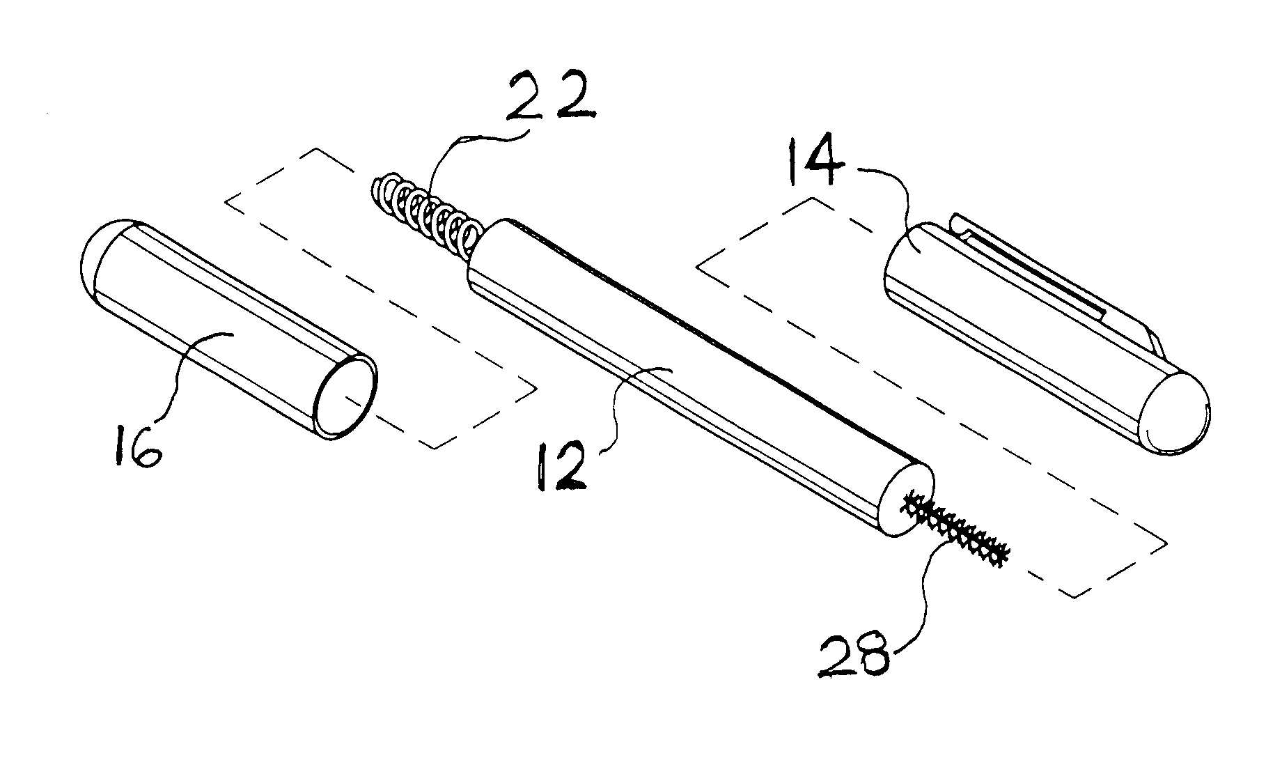
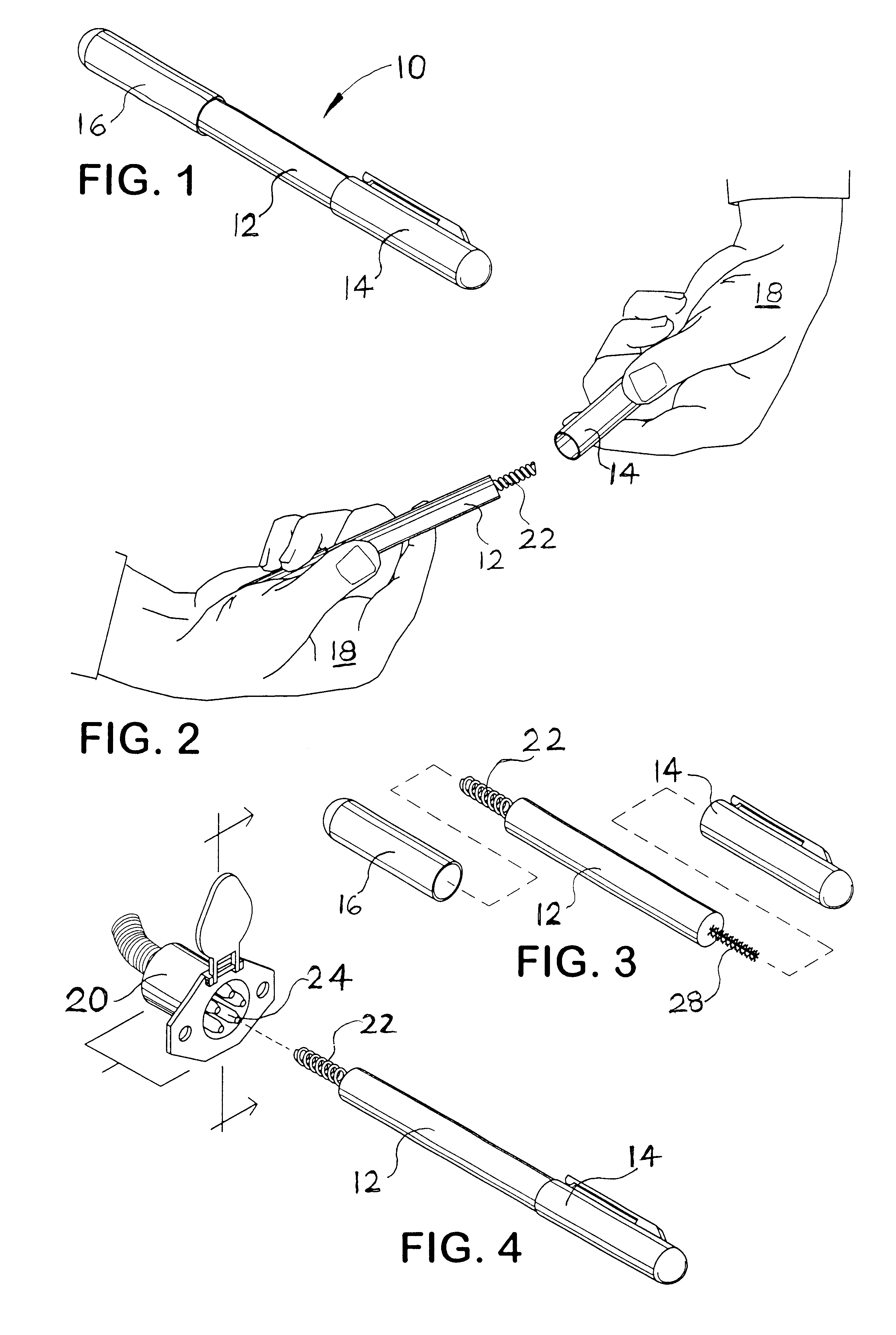
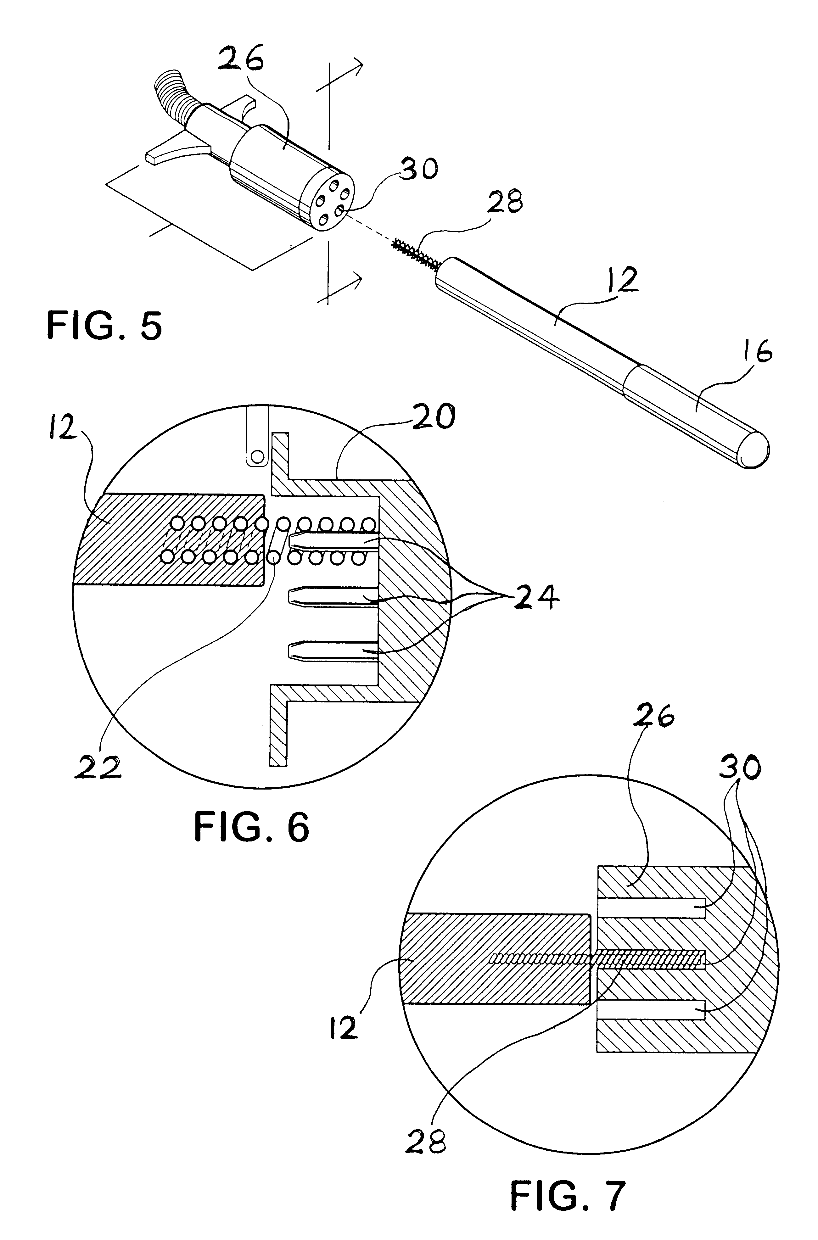
Referring to FIG. 1, a perspective view of a preferred embodiment of the trailer electrical connector cleaning system 10 (the "system 10" hereinafter) of the present invention is shown. The system 10 preferably comprises a terminal-cleaning element body 12, a pocket clip protective cap 14, and a protective cap 16. Such a system 10 embodies herein at least one cleaning structure arranged to enable an axial linear and axial rotational cleaning motion to be applied to a trailer-electrical-connector electrical terminal. Referring to FIG. 2, another perspective view of a preferred embodiment of the system 10 of the present invention is shown depicting a user 18 removing the protective cap 14 from over the male terminal-cleaning element 22 of the terminal-cleaning element body 12. The protective cap 14 is preferably a friction, or snap-fit cap that slides over the male terminal-cleaning element 22 of the terminal-cleaning element body 12. As shown, the system 10 is very small, compact, an...


PUM


Abstract

A system for the cleaning of male and female terminals comprised within electrical connectors. The system is a small, compact, portable system that comprises at least one cleaning element wherein the cleaning element may be a brush cleaning element, or alternatively may be a helical cleaning element, and wherein the cleaning element may be used for the cleaning of female electrical terminals. Further, the system may comprise an additional helical cleaning element that may be used for the cleaning of male electrical terminals. The system further comprises enclosing structure that isolates the cleaning element, or elements, from the environment to prevent the dropping of debris from the cleaning elements into the pocket of a user carrying the cleaning system. The system further comprises a pocket clip for the carrying of the system.

Description

1. Field of the InventionThis invention relates to providing electrical terminal-cleaning systems. More particularly, this invention provides a system for the cleaning of male and female terminals comprised within trailer electrical connectors.2. Description of the Prior ArtTrailer electrical connectors carry the power to illuminate the trailer lights, charge auxiliary batteries, activate braking systems, etc. Such trailer electrical connectors generally comprise substantially round body connectors having a plurality of individual electrical terminals therein. Such electrical connectors comprise male and female electrical terminals that are preferably designed to mate with one another, thus, forming a low resistance path for electrical current flow. However, due to the exposure of such trailer electrical connectors to the elements, the male and female electrical terminals often become covered in dirt or corrosion that will prevent a satisfactory electrical contact between the male a...

Claims


Application Information

Patent Timeline
Patent Type & Authority Patents(United States)
IPC IPC(8): B08B1/00H01R43/00B08B9/027
CPCB08B1/00H01R43/002
Inventor ROOKE, CRAIG T.
Owner ROOKE CRAIG T
Learn More