Clamping apparatus

a technology of clamping apparatus and bolt, which is applied in the direction of nuts, couplings, rod connections, etc., can solve the problems of not being able to precisely predict the position of threaded bolts or shafts, and achieve the effects of high repeatability, fast fixation, and easy maintenan

Inactive Publication Date: 2004-03-09
EROWA
View PDF10 Cites 2 Cited by
  • Summary
  • Abstract
  • Description
  • Claims
  • Application Information

AI Technical Summary

Benefits of technology

It is an object of the invention to provide a clamping apparatus for fixing and non-rotatably clamping threaded shafts that avoids the afore mentioned disadvantages, i.e. to provide a clamping apparatus in which a threaded shaft can be fixed quickly, easily and with high, repeatable accuracy.
In order to meet this and other objects, the invention provides an apparatus for fixing and non-rotatably clamping threaded shafts comprising a hollow tubular housing having a central longitudinal axis. The hollow tubular housing comprises an aperture extending in radial direction with regard to the central longitudinal axis and has a rectangular cross sectional shape. A clamping element is slidably received in that aperture and has a front face provided with thread convolutions. An operating element is provided to slidably move the clamping element received in the aperture towards the central bore and to lock a threaded shaft inserted into the central bore with high positional accuracy and repeatability.
Due to the rectangular shape of the aperture and the clamping element, it is ensured that the position of the clamping element with regard to the clamping apparatus does not change, with the result, that a threaded shaft is clamped in the apparatus always in exactly the same axial position.

Problems solved by technology

A fundamental disadvantage of the afore mentioned devices can be seen in the fact that the position of a threaded bolt or shaft is not exactly defined nor can be exactly predicted.

Method used


Image

  • Clamping apparatus
  • Clamping apparatus

Examples


Embodiment Construction

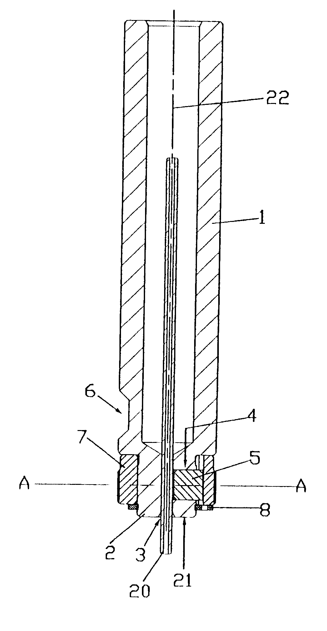
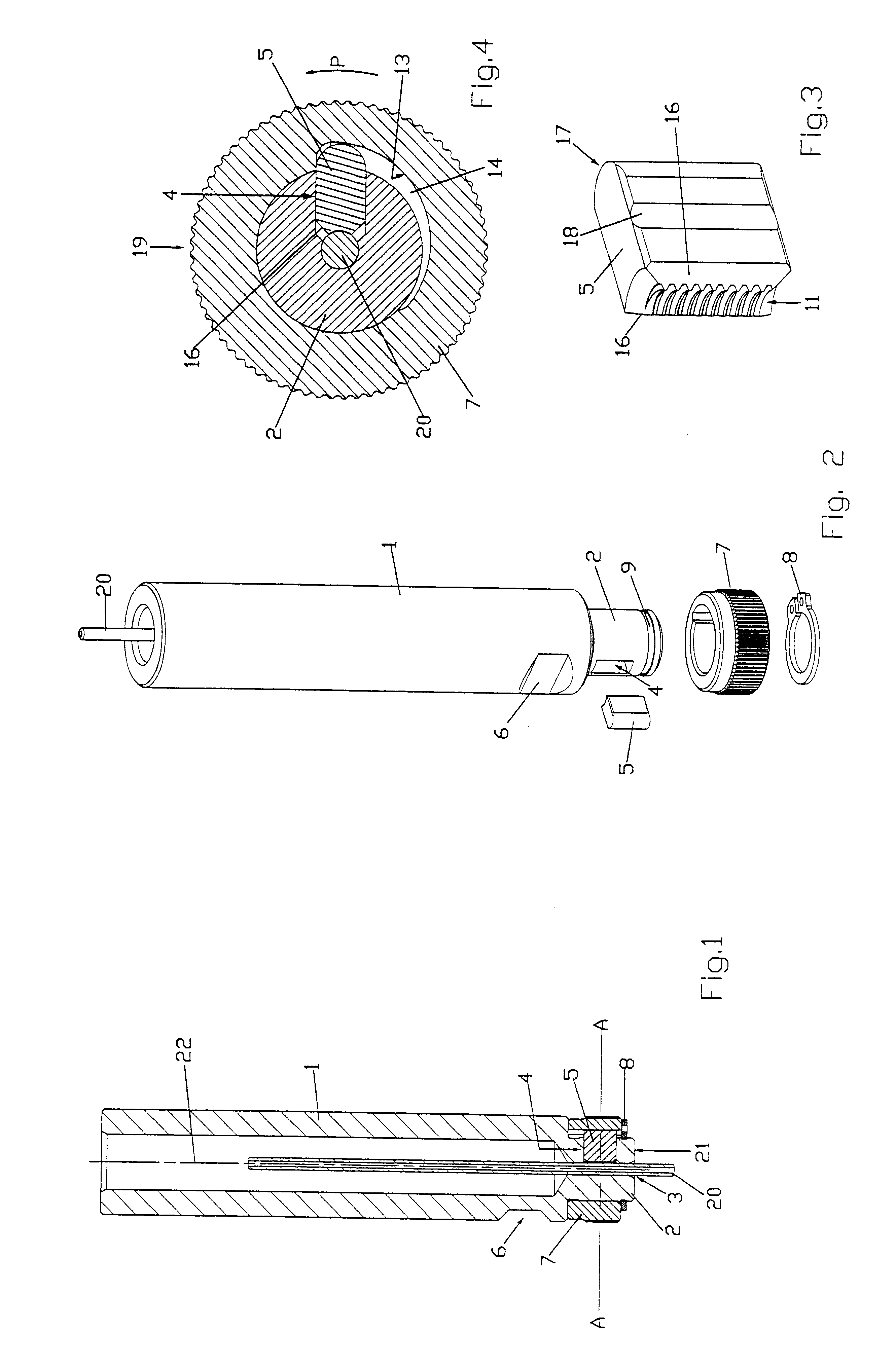
According to FIG. 1, the clamping apparatus comprises a hollow cylindrical shaft member 1. The front portion thereof, i.e. the lower portion as shown in FIG. 1, is provided with a cylindrical clamping sleeve member 2. The clamping sleeve member 2 has a central bore 3 adapted to receive a threaded shaft 20. It is understood that the diameter of the central bore 3 matches the external diameter of the threaded shaft 20 to be received therein.

The clamping sleeve member 2 is provided with an aperture 4 opening into the central bore 3. The aperture 4 is adapted to receive a radially movable clamping element 5, to be described in more detail herein below, and having generally rectangular cross section. In this connection, radially movable shall mean towards and away from the threaded shaft 20 received in the bore 3. The aperture 4 has a cross section whose width and height is adapted to the dimensions of the clamping element 5 such that the latter one slides in the aperture 4 with essentia...


PUM

PropertyMeasurementUnit
outer diameteraaaaaaaaaa
diameteraaaaaaaaaa

Abstract

A clamping apparatus for fixing and non-rotatably clamping threaded shafts, particularly threaded shafts used as electrodes for eroding threads, comprises a hollow cylindrical shaft with a clamping sleeve member located at its front end. The clamping sleeve member has a central bore and a rectangular aperture opening into that central bore. A rectangular clamping member is slidably received in the aperture and comprises at its front surface, facing the central bore, a number of thread convolutions matching the thread convolutions of the shaft to be clamped. For moving the clamping element towards a threaded shaft received in the central bore, a rotating collar is provided, located around the outside of the clamping sleeve member, and having a an inner circular surface with a diametrically gradually enlarging recessed portion into which the clamping element protrudes. By rotating the collar, the clamping element is radially moved toward a threaded shaft inserted into the bore, until the thread convolutions of the clamping element engage the thread convolutions of the shaft in the bore.

Description

The present invention refers to a clamping apparatus for fixing and non-rotatably clamping threaded shafts, particularly threaded shafts used as electrodes for eroding threads.In order to fix and clamp, respectively, threaded shafts used as electrodes for eroding threads, usually clamping devices in the kind of split chucks or collet chucks are used that are inserted in a corresponding chuck holding device and clamped therein. The threaded shaft to be firmly held in place is inserted into the central opening of the split chuck and clampingly fixed in the desired position. This kind of fixing has two fundamental disadvantages. First, only the crests of the thread convolutions rest against the inner wall of the split chuck and are clamped therein, with the result that the thread convolutions could be damaged, particularly in the case of V-threads. Second, the position of the thread with regard to the split chuck and the chuck holder, respectively, is not exactly defined. The result is...

Claims


Application Information

Patent Timeline
Patent Type & Authority Patents(United States)
IPC IPC(8): B23H7/26B25B5/00B25B5/14F16B37/08B25B15/00
CPCB23H7/265B25B5/147Y10T403/598Y10T403/591Y10T403/7069F16B37/0864B23H9/003B25B15/00
Inventor FRIES, KARL
Owner EROWA
Why Eureka
Try Eureka