Lubrication system for outboard motor shaft coupling

a technology of lubrication system and outboard motor, which is applied in the direction of propulsive elements, marine propulsion, vessel construction, etc., can solve problems such as coupling damag

Inactive Publication Date: 2004-03-09
YAMAHA MARINE KK
View PDF13 Cites 3 Cited by
  • Summary
  • Abstract
  • Description
  • Claims
  • Application Information

AI Technical Summary

Problems solved by technology

During normal use, however, the grease may lose its efficacy and may dry, thus leaving the coupling dry and unlubricated, which can damage the coupling, either because of burning and / or rusting.

Method used


Image

  • Lubrication system for outboard motor shaft coupling
  • Lubrication system for outboard motor shaft coupling
  • Lubrication system for outboard motor shaft coupling

Examples


Embodiment Construction

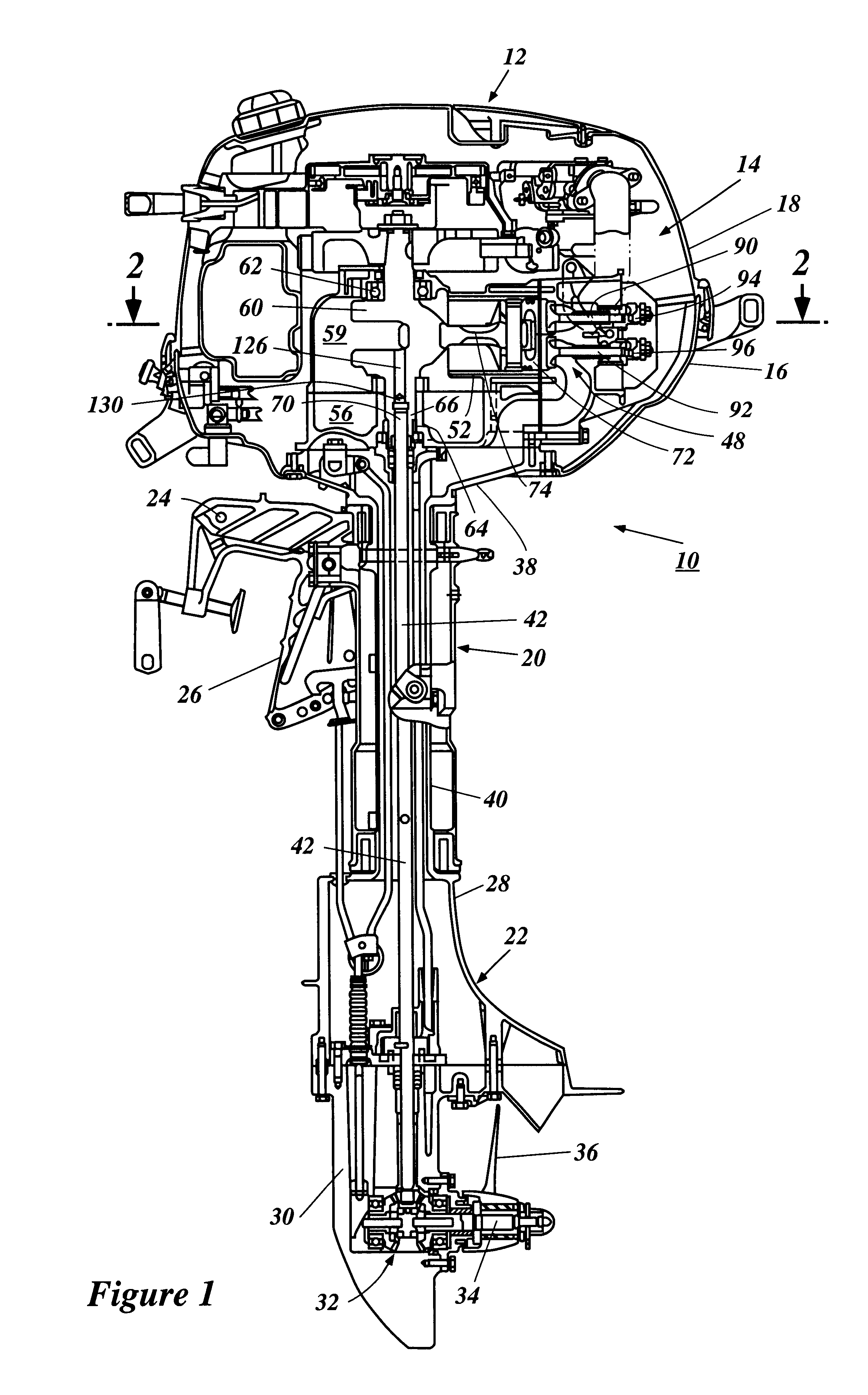
With reference to the drawings and initially to FIG. 1, an outboard motor constructed in accordance with an embodiment of the invention is identified generally by the reference numeral 10.

The outboard motor 10 is comprised of a power head, indicated generally by the reference numeral 12, and a lower unit assembly, indicated generally by the reference numeral 22. The power head 12 includes an internal combustion engine 14, which is shown partially in cross-section in FIG. 1. While embodiments disclosed herein generally reference the use of a four-cycle internal combustion engine, it should be apparent to those of skill in the art that the lubrication system disclosed herein may also be used in engines operating on two-cycle combustion principles. The lubrication system can also be used with engine employed in other applications (e.g., lawn mowers) in which the engine is stood generally upright (i.e., the rotational axis of the engine is upright).

The power head 12 is covered primarily...


PUM


Abstract

A lubrication system is provided that allows delivery, and preferably regulated delivery, of lubricant to a coupling between a crankshaft and the driveshaft of, for example, an outboard motor. The lubrication system includes a passageway through which lubricant flows, and preferably a flow restrictor regulates the amount of lubricant delivered through the passageway. In one mode, the passageway is generally formed vertically through the central axis of a vertically oriented crankshaft and extends between the crankcase chamber and the coupling. Lubricant, such as crankcase oil, is able to flow through the passageway and onto the coupling. One or more seals preferably inhibit lubricant from flowing beyond the coupling.

Description

PRIORITY INFORMATIONThis application is based on and claims priority to Japanese Patent Application No. 2001-193862, filed on Jun. 27, 2001, the entire contents of which is hereby expressly incorporated by reference.1. Field of the InventionThis invention relates to an engine for an outboard motor and more particularly to an improved lubrication system for an outboard motor.2. Description of the Related ArtOutboard motors typically have an internal combustion engine that is coupled to a propulsion unit, such as a propeller, for propelling the boat through the water. The internal combustion engine includes one or more pistons reciprocally connected to a crankshaft for rotation during the combustion process. The crankshaft, in turn, is typically spline-coupled to a driveshaft that transmits the engine torque through a bevel-gear transmission and to a propeller shaft which carries the propeller. Thus, the engine output is transmitted from the crankshaft to the driveshaft and ultimately...

Claims


Application Information

Patent Timeline
Patent Type & Authority Patents(United States)
IPC IPC(8): F01M11/02B63H21/38B63H20/00F01M1/06F01M9/08F02B67/00F16N7/14
CPCB63H21/38F01M11/02B63B2770/00F01M2001/062B63H20/002
Inventor KAMEOKA, KENTARO
Owner YAMAHA MARINE KK
Why Eureka
Try Eureka