
Cylindrical battery and method for manufacturing the same

Inactive Publication Date: 2004-03-09
PANASONIC CORP
View PDF11 Cites 18 Cited by
  • Summary
  • Abstract
  • Description
  • Claims
  • Application Information

AI Technical Summary

Benefits of technology

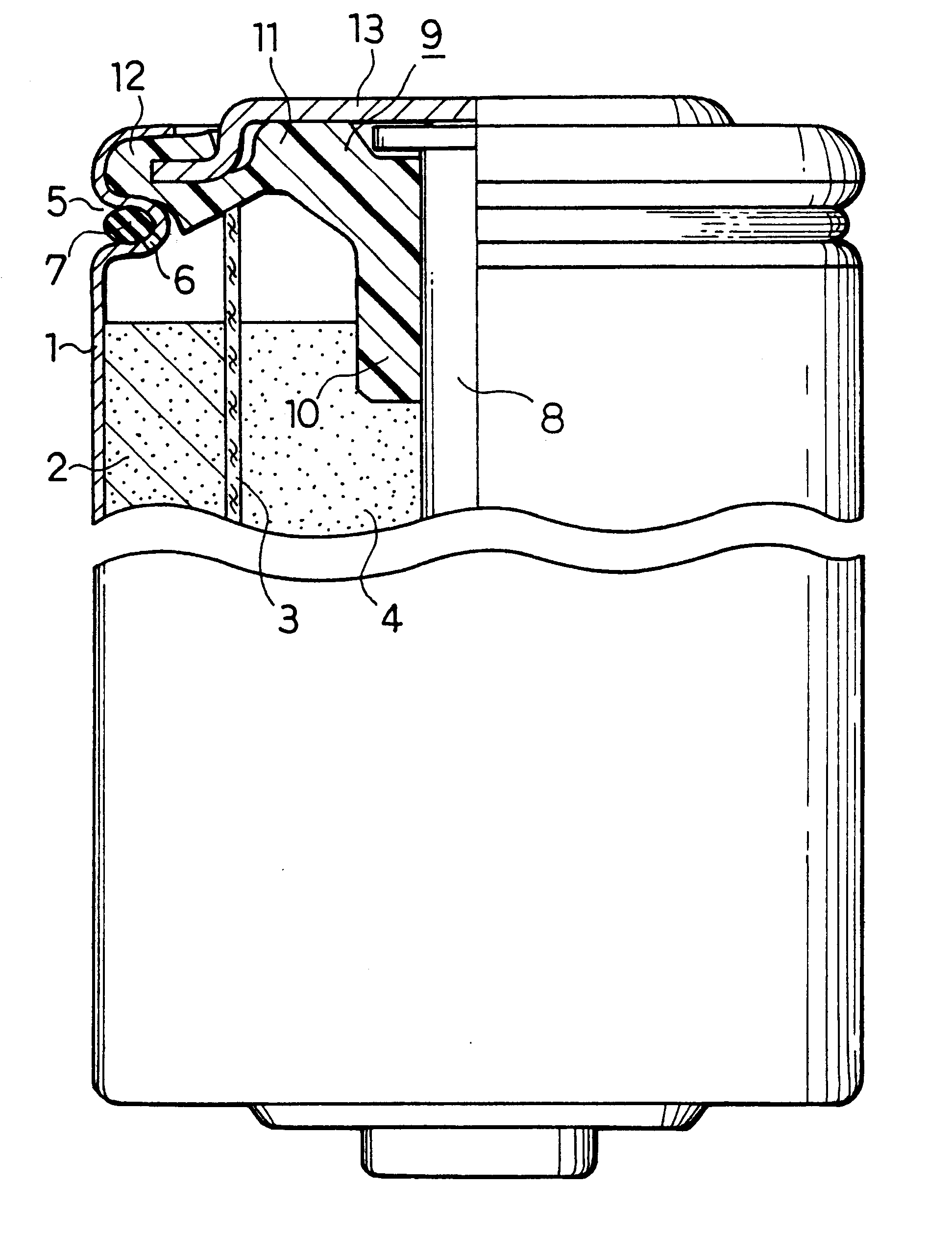
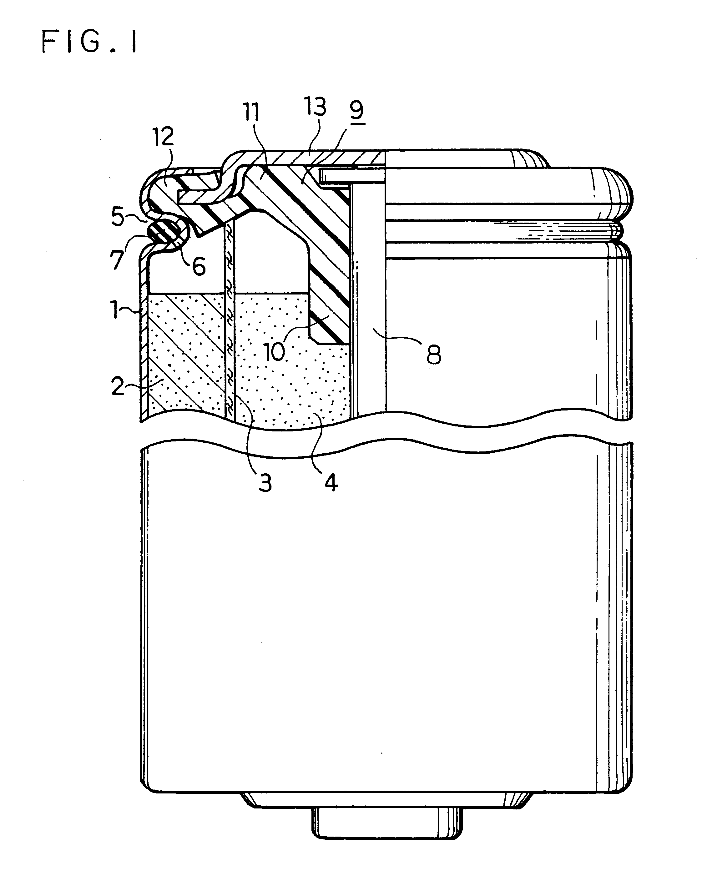
It is preferable that the elastic ring has a substantially circular cross section and is held inside the groove. The elastic ring is held inside the groove by pressing down and deforming the opening end of the battery case towards the bottom of the battery case to narrow the opening circumference of the groove. This arrangement enhances the effects of the elastic ring to seal the gas discharge aperture and thereby improves the leakage proof ability.
Application of a sealing agent layer on a face of the elastic ring that is in contact with the groove further improves the leakage proof ability. Application of a water repellent on a circumferential portion of the gas discharge aperture inside the battery case still further improves the leakage proof ability.

Problems solved by technology

In alkaline batteries having zinc as the anode active material, there is a fear that a gas is produced inside the battery, due to the wrong charge or the corrosion of zinc, so as to increase the internal pressure of the battery and even lead to an explosion of the battery.
As clearly understood from FIG. 5, the prior art burst-proof mechanism has a rather complicated structure and located inside the battery.
The space required for the burst-proof mechanism sacrifices the capacity for the power generating elements.
This accordingly does not work as the burst-proof mechanism, and may lead to an explosion of the battery.

Method used


Image

  • Cylindrical battery and method for manufacturing the same
  • Cylindrical battery and method for manufacturing the same
  • Cylindrical battery and method for manufacturing the same

Examples


example 2

This example describes a battery with a non-reset type burst-proof mechanism.

FIG. 4 shows the structure of an alkaline battery of this example. In this figure, the same numerals as in FIG. 1 denote the same elements as in FIG. 1. In the structure of this example, one gas discharge aperture 6 is formed in the bottom of the groove 5 and sealed by a seal element 7' composed of a hot-melt adhesive. A jacket label 19 is composed of a heat-shrinkable resin and has a print of a trade mark, a grade of the battery, or the like.

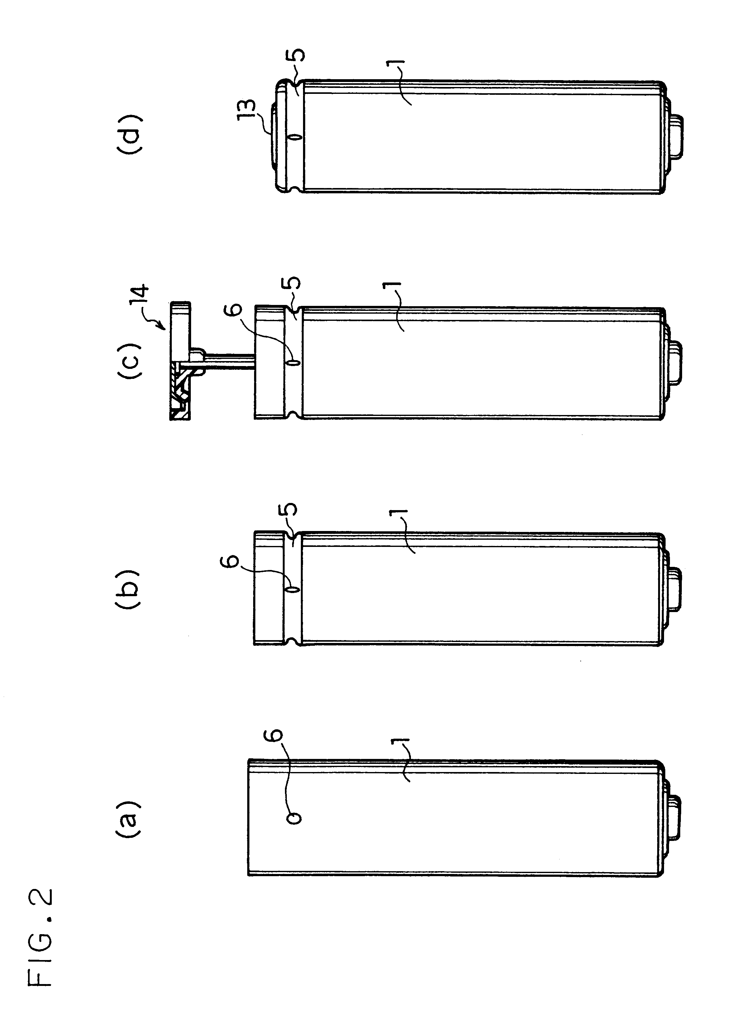
In this example, the seal element 7' has a ring shape. The ring-shaped seal element 7' is provided, for example, by ejecting a fused hot-melt adhesive into the groove 5 from an ejector while the battery case 1 is rotated in the step of FIG. 3(e).

The seal element 7' may not have a ring shape but be simply stuck to the circumferential part of the gas discharge aperture 6, so as to seal the gas discharge aperture. In this case, since there is a fear that the seal element ...


PUM


Abstract

The present invention provides a high-capacity cylindrical battery, wherein a burst-proof mechanism, which functions to discharge a gas outside when the internal pressure of the battery abnormally increases, does not sacrifice the space for power generating elements but increases the total capacity for power generating elements. The cylindrical battery of the present invention has a circular groove formed in the vicinity of an opening of a battery case, in which power generating elements are accommodated, the circular groove having a bottom that is bent inward the battery case and has at least one gas discharge aperture, which is sealed with a seal element. The seal element is an elastic ring to be set in the groove and seal the gas discharge aperture. This arrangement enables the gas discharge aperture to be sealed again even after the burst-proof mechanism functions, thereby ensuring a continuous use of the battery.

Description

The present invention relates to a cylindrical battery, such as an alkaline battery or a lithium battery, in which power generating elements are accommodated in a cylindrical battery case and an opening of the battery case is sealed with a sealing member, as well as to a method for manufacturing such a cylindrical battery.In alkaline batteries having zinc as the anode active material, there is a fear that a gas is produced inside the battery, due to the wrong charge or the corrosion of zinc, so as to increase the internal pressure of the battery and even lead to an explosion of the battery. The alkaline batteries thus generally have a burst-proof mechanism, which functions in response to an increase in internal pressure of the battery to avoid a possible explosion.The principle of the burst-proof mechanism is to intentionally break a specific part of lowered mechanical strength, which is a portion of a sealing member to seal the opening of the battery, on the occasion of an increase...

Claims


Application Information

Patent Timeline
IPC IPC(8): H01M2/04H01M2/12H01M6/06H01M10/04H01M10/24H01M10/52H01M50/119H01M50/124
CPCH01M2/027H01M2/0275H01M2/0421H01M2/12H01M2/1229H01M10/52H01M2/022H01M6/06H01M10/24Y02E60/10H01M50/107H01M50/545H01M50/154H01M50/325H01M50/30Y02P70/50H01M50/124H01M50/119
Inventor SHOJI, YASUHIKOKUBO, ISAOYAMAMOTO, KENJIMOTOTANI, YUJI
Owner PANASONIC CORP
Learn More