
Storage and display units for cards and the like and methods of making same

a technology of display units and cards, applied in the directions of pile separation, transportation and packaging, chutes, etc., can solve problems such as continuing problems

Inactive Publication Date: 2004-03-16
MCGRAW BRUCE ARNOLD
View PDF9 Cites 8 Cited by
  • Summary
  • Abstract
  • Description
  • Claims
  • Application Information

AI Technical Summary

Benefits of technology

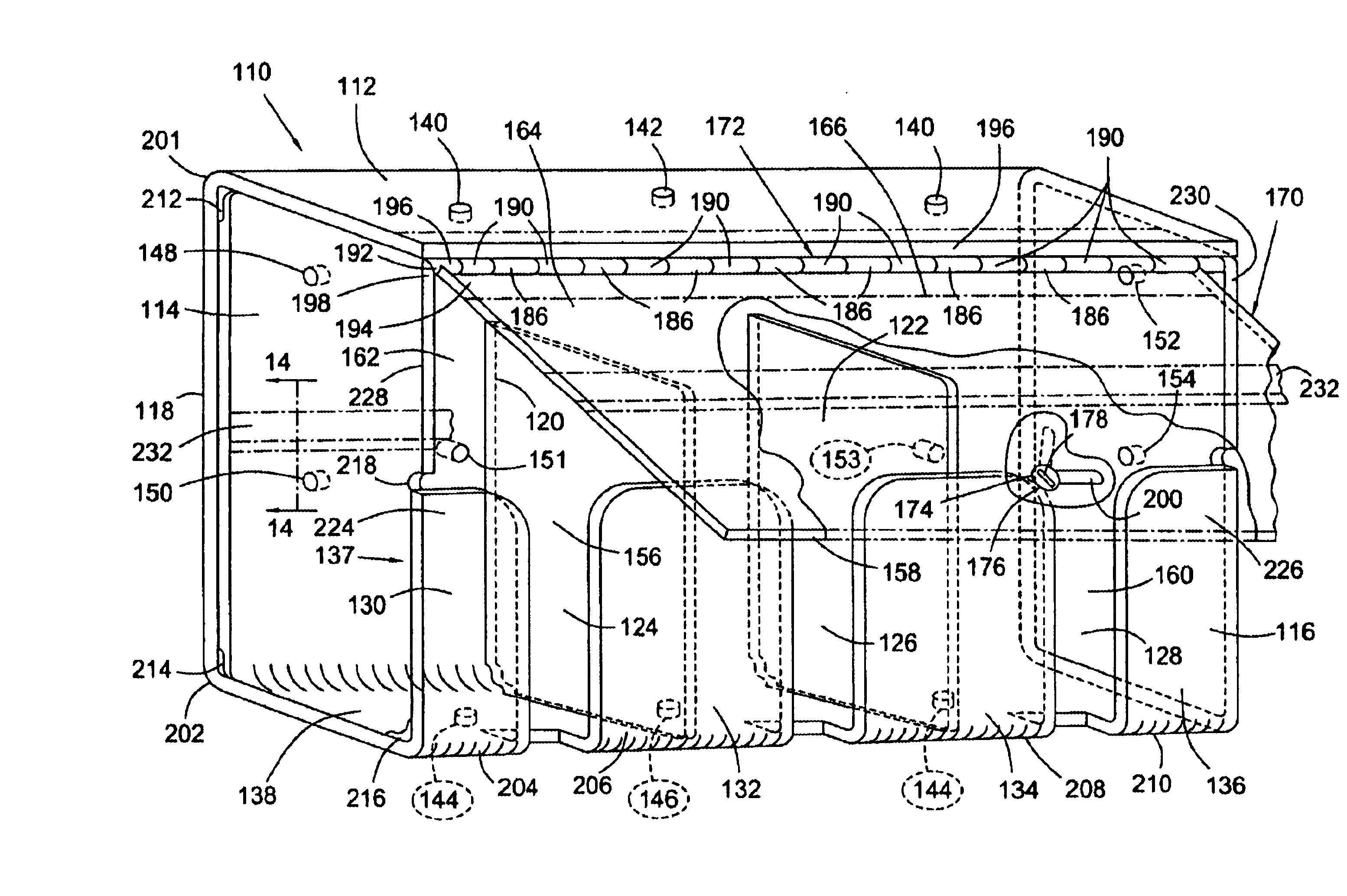
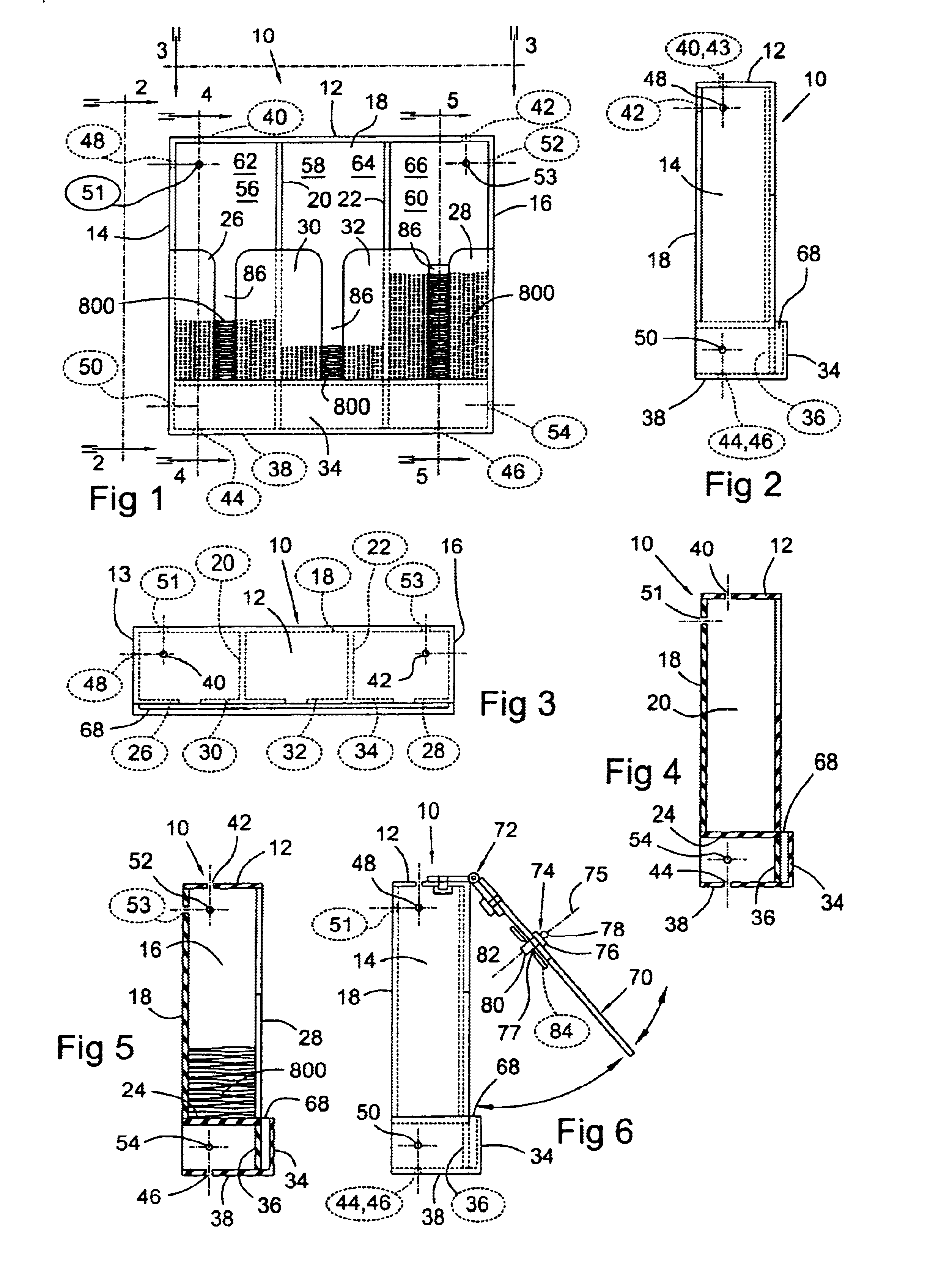
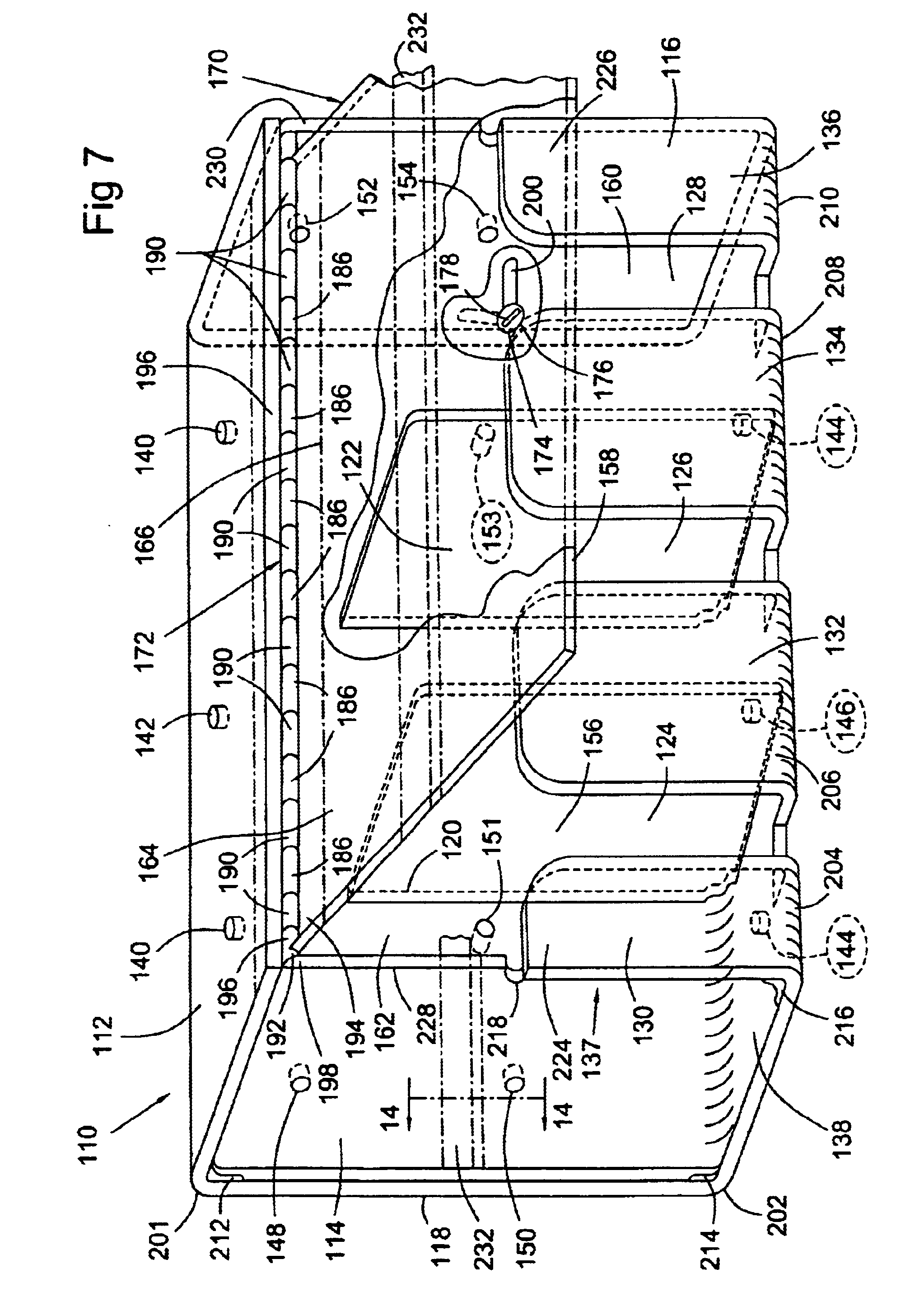
Another object of the invention is to provide a cover hinged to the top of a unit for swingable movement from a vertical position, in which the one or more T-shaped openings, depending upon the number of bins, are covered by the cover, to an open position in which the one or more T-shaped openings are at least sufficiently open and uncovered by the cover so as to permit the installation and removal of cards into and from the one or more bins. It is also preferable that the cover has a key-operated security lock thereon with a movable locking bar movable about the lock axis by key action only from an unlocked position to a locked position and back to an unlocked position, the locked position being such position that the lock axis extends through a T-shaped opening and the locking bar engages the bin interior side of at least one of the spaced parts of the front defining the T-shaped opening while the cover is in its vertical position covering the T-shaped opening. The lock bar is also movable by the key lock to a position wherein it is disengaged from the at least one of the spaced parts of the front defining the T-shaped opening and is in alignment with a part of the T-shaped opening so as to permit the cover to be swung to its position wherein the T-shaped opening, or openings in the case of a plurality of bins having been provided, is uncovered to permit the installation and removal of cards into and from the one or more bins. The lockable and unlockable cover thus keeps the cards secure from inadvertent or intentionally impermissible removement from any bin.
Yet another object of the invention is to have the lock bar extending to only one side of the lock axis so as to be engageable with and disengageable from only one of the at least one of the spaced parts of the unit front defining a T-shaped opening. The lock bar is rotated only about 90.degree. in arc from its engageable position to its disengageable position so that, as the cover is raised, the lock bar exits the bin through the vertical part of the T-shaped opening. Alternatively, the bar may extend to both sides of the lock axis so as to be engageable with and disengageable from both of the two spaced parts of the front defining the T-shaped opening. Such a lock bar then is rotated about 180.degree. in arc from its engageable position to its disengageable position when the unit is to be unlocked. If desired, the bar may be formed substantially as a semi-circle and in its unlocked position is above the lock axis when it is in the unlocked position so as to be in alignment with the T-shaped opening upper part and in disengageable relation with the spaced parts of the front side defining the T-shaped opening. When it is in its locked position it extends below the lock axis so as to be in engageable relation with both of the two spaced parts of the front side defining the T-shaped opening, preventing swinging movement of the cover to uncover the T-shaped opening as well as any other T-shaped openings for additional bins.
Another feature of the invention which may be used is the provision of a card-retainable strip secured to the cover on the side thereof facing the bin or bins when the cover is covering all T-shaped openings, permitting one side of a card retained therein to be visually observed by a customer through the transparent cover while the cover covers the T-shaped openings. Any cards in the one or more bins are accessible to a clerk because the one or more bins are openable only by a clerk having a key for operating the key lock, thereby providing security against unauthorized removal of a card from any bin. Alternatively or in addition, a card-retainable strip may be secured to the unit back on the side thereof facing the bin or bins, permitting one side of a card retained therein to be visually observed through the transparent back, so that the back may be the side of the unit seen by a customer and the closed cover being the side being accessible to a clerk and openable by a clerk having a key for operating the key lock, thereby providing greater security against unauthorized removal of a card from any bin. This latter arrangement is very desirable when the unit is sitting on a counter top with the customer on one side and a clerk on the other side.
Another feature of the invention is the provision of a card-retainable strip secured to unit back and / or to the cover on the side thereof facing the bin, permitting one side of a card retained therein to be visually observed through the back or the cover, or both. When such a card is visible through the back, the back may be the side of the unit seen by a customer and the closed cover being the side being accessible to a clerk and openable by a clerk having a key for operating the key lock, thereby providing greater security against unauthorized removal of a card from said bin. When there is a card visible through the back and another one of the same issue visible through the closed cover, both the customer and the clerk have an opportunity to quickly identify the cards in the particular bin relating to those cards. When there is a card visible through only the closed cover, the customer can still identify the particular in that related bin, and if there are such cards placed to be seen through the closed cover for each bin covered by the cover, the customer can see all of them and make a choice as to the card he prefers. The clerk can then either move the unit around so that the closed cover faces him, and then unlock it to remove the card of the customer's choice, or be on the same side of the unit as the customer, and so remove the card selected.
(1) creating a first planar pattern for the bottom, back side and front side; (2) precisely cutting a single substantially transparent plastic part from a planar sheet of plastic having a thermoplastic pliable characteristic permitting bending of the plastic part at controlled bending radii under controlled applied heat; (3) bending the single plastic part under controlled applied heat applied at the areas thereof joining the bottom to the back side and to the front side at controlled radii of bending so that the planes of the back side and the front side are parallel in spaced relation to each other and are perpendicular to the plane of the bottom; (4) cooling the single plastic part to cool the material thereof at the points thereof having had applied heat until the single plastic part is stable in the parallel and perpendicular relationships set forth and is no longer thermoplasticly pliable so as to be bendable as was done in step (3); (5) creating a second planar pattern for the left and right side panels; (6) precisely cutting the left and right side panels from a planar sheet made of the same plastic as the single plastic part was cut; and (7), after step (4) has been completed, securing the left and right side panels to the single plastic part to provide closed side panels with at least one interior bin so enclosed.

Problems solved by technology

Experience has shown that this is a continuing problem with current card holding units.
Units may be secured to a wall, shelf, counter or other device, including pegboard, for example, so that the units are not free-standing and therefore tempting sales persons, or others, to pick up the entire unit.

Method used


Image

  • Storage and display units for cards and the like and methods of making same
  • Storage and display units for cards and the like and methods of making same
  • Storage and display units for cards and the like and methods of making same

Examples


Embodiment Construction

The unit 10 shown in the drawing FIGS. 1-6 is a three-bin unit which will accommodate the three most common telephone card denominations of $5, $10 and $20 in United States currency. In FIGS. 8 through 13, described later, cards in any bin of any unit are identified by the reference character 800. In other countries, of course, they will accommodate cards 800 of their most common denominations. The unit may be made of several parts which are secured together in a suitable manner such as gluing or plastic welding, or the unit may be integrally injection molded either as a single part or, when cost of mold design or other factors dictates, is only two or three parts (and seldom more, although that can be done within the purview of the invention). When units are made by injection molding, the edges and corners may be rounded to accommodate mold requirements, and such rounding will also contribute to the attractiveness of the unit.

Unit 10 has the following parts, it being understood tha...


PUM

PropertyMeasurementUnit
Angleaaaaaaaaaa
Angleaaaaaaaaaa
Transparencyaaaaaaaaaa

Abstract

A storage and display unit for prepaid telephone calling cards, collectible cards, and the like which is made, at least in a major part, of a substantially transparent plastic having a reasonable amount of impact resistance to breakage, the unit being combinable with other units to assemble larger units, the unit providing one or more bins holding cards that are for sale, with the cards in view through the transparent portions of the unit, and arranged to have a key-lockable cover to at least deter unauthorized removal of cards. The unit also provides for display of a card's face to indicate the type of card in each card bin. The display can be arranged to be on the front or back of the unit, or both. When on the back, the unit is best oriented so that the display card seen through the transparent unit back is facing customers, and the locked cover is facing the clerk or other salesperson who has a key and is authorized to remove cards for sale. When the display card is also on the locked cover, it provides quick visual identification of the various cards in various bins. Individual units, having one or several bins, can be attached in horizontal or vertical array, or both, to form larger display units having more bins. Processes for making and assembling the units are also disclosed, preferably using a thermoplastic material which is heated at bend points to become pliable, and bent to combine what would otherwise be several individual unit panels into one piece. A jig for heating and bending a blank patterned part is also schematicly disclosed.

Description

SUMMARY OF THE INVENTION OR INVENTIONS DISCLOSEDBroadly, the invention or inventions disclosed herein are directed to storage and display units providing card bins for visible storage of cards which are readily accessible for removal as cards are sold, and providing space for a card of the type as contained in each card bin for displaying the card, and the methods of making such units. Units are preferably made of a material such as high density polyethylene, rendering it much more resistant to the currently commonly used cardboard units when it is accidentally dropped. They may also be made of well-known acrylic material. Units embodying the invention provide arrangements for holding the cards and accessing them when a sale is being made, providing easy access so that the sales person no longer needs to pick up the entire unit to retrieve a card, thus making it much less likely that the unit will be dropped. Experience has shown that this is a continuing problem with current card h...

Claims


Application Information

Patent Timeline
IPC IPC(8): A47F1/00A47F1/06A47F7/14B29C53/04B29C53/00B29C53/84
CPCA47F1/06A47F7/142B29C53/04B29C53/84
Inventor MCGRAW, BRUCE ARNOLD
Owner MCGRAW BRUCE ARNOLD
Learn More