
Driving device for a hydroacoustic transmitter

a technology of driving device and hydroacoustic transmitter, which is applied in the direction of sound producing device, mechanical vibration separation, instruments, etc., can solve the problems of transmitters having difficulty in generating high amplitudes below 100 hz, the device efficiency is strongly reduced at such frequencies, and the shell presents a number of oscillation modes

Inactive Publication Date: 2004-03-23
CETUS CORP
View PDF5 Cites 34 Cited by
  • Summary
  • Abstract
  • Description
  • Claims
  • Application Information

AI Technical Summary

Benefits of technology

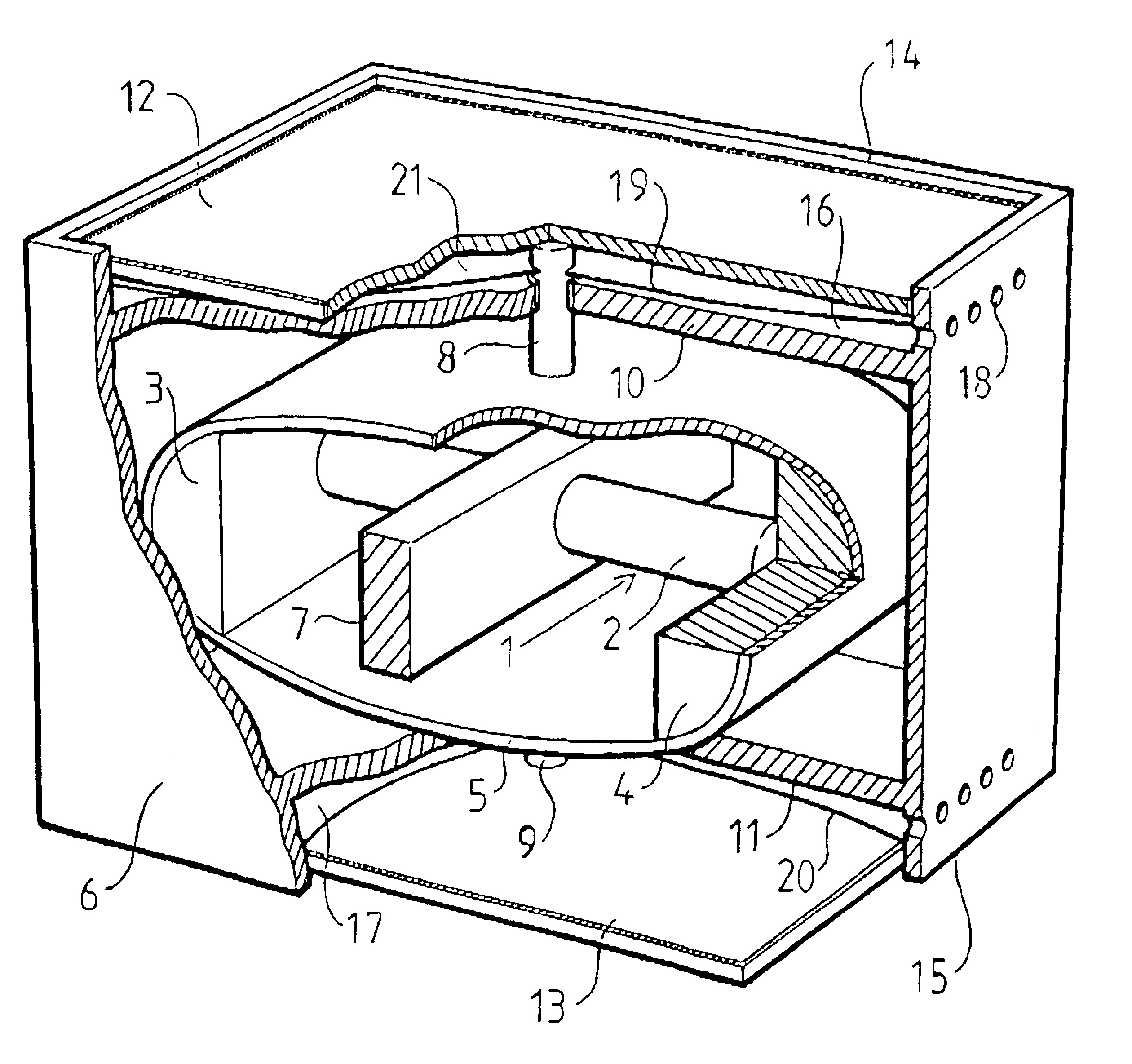
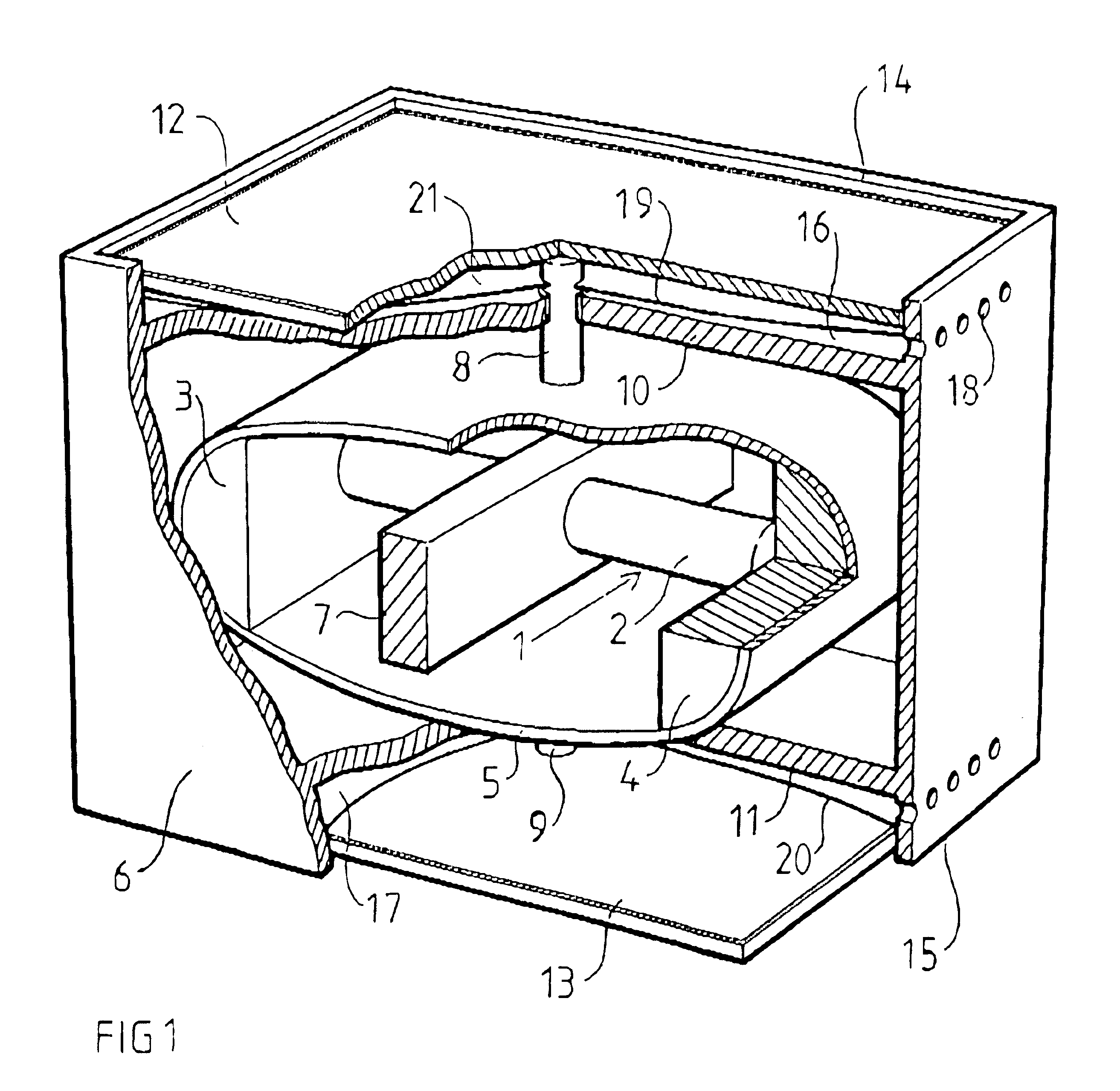
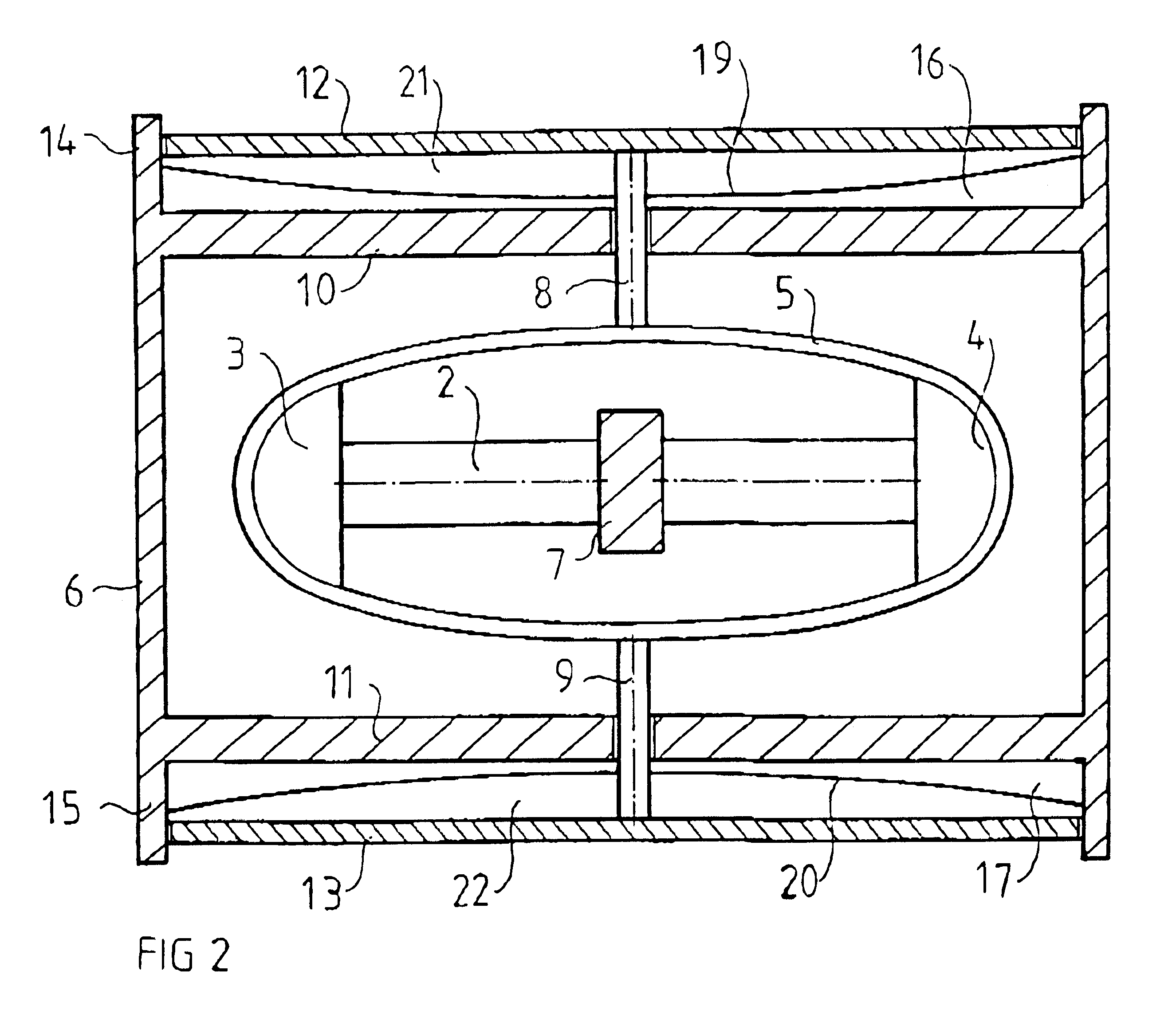
According to a further preferred embodiment, the device includes at least one transmission element, via which the spring member is connected to the displacement element and via which the movement of the spring member is transmitted to the displacement element and generates a displacement thereof, which results in said mass displacement. Advantageously, the transmission element can be one or more rods or the like, which at one of the ends is / are attached to an, in a movement point of view, optimal part of the spring member and at an opposed end is / are attached to an advantageous part of the displacement element. Also the mass of the transmission element can be utilized to control the frequency characteristic of the device. Thus, the displacement element can be employed to provide a larger transmission ratio of the device, especially if it, via the transmission element, is connected to the part of the spring member where its reciprocating movement is the largest and most reliable with respect to interference etc. At generation of hydroacoustic waves, the displacement element may, for instance, be a stiff plate, which is displaced perpendicularly to its plane of propagation, and acts against a liquid. The area of the plate does principally not have to be limited by the size or length of the actuating element or the size or the length of the spring member, and thanks to its shape and stiffness, interference problems are avoided, which easily appear when an elliptical structure is operating both as a spring member and a displacement element.
According to a further preferred embodiment, the device includes a container, inside which the actuating element and the spring member are arranged, and outside which the displacement element is arranged. A transmission element can advantageously be arranged so that it tightly penetrates a wall of the container. Thanks to the described design, the spring member and the actuating element are protected against direct outer influence. Preferably, the container is impermeable and filled with a gas-like medium or vacuum. Provided that the container is of a rigid design, the device can be conveyed down to a large depth in the liquid, and the actuating element as well as the spring member will be well protected against outer agitation, for instance powerful pressure waves, caused by under-water explosions or the like. Thanks to the fact that the driving element and the spring member are surrounded by a gas or vacuum, the spring member can operate without directly being affected by any resistance from a surrounding liquid.
According to a further preferred embodiment, the device includes a substantially immovable fixture, which sealingly surrounds the displacement element and relatively which the latter is displaced during its displacement movement, and includes a resilient membrane which between itself and the displacement element encases a gas and is attached to said fixture, whereby the membrane and the encased gas are arranged between the displacement element and the wall, which the transmission element goes through. When the device is immersed into a liquid and the surrounding liquid pressure increases, the gas pressure between the membrane and the displacement element will increase. Since the membrane and the encased gas are arranged between the displacement element and the wall which the transmission element goes through, the gas pressure will counteract that the displacement element is displaced towards the spring member and influences it with a force due to the increased surrounding liquid pressure. To achieve this effect, the device must be designed with channels or the like to admit liquid, which surrounds the device, entrance to a space between the membrane and said wall. By such an arrangement of the fixture, the flexible membrane, and the gas, a self-compensating pressure equalization is achieved, resulting in the fact that the function of the device can be made independent of the application depth. Furthermore, the actuating element and the spring member are protected against violent shocks, or the like from outside for instance from pressure waves caused by under-water explosions, or the like.

Problems solved by technology

However, the shell presents a number of modes of oscillation, depending i.a. on its shape, deadweight and stiffness.
At certain frequencies, however, interferences between higher modes are obtained, which leads to the fact that the efficiency of the device at such frequencies is strongly reduced.
Normally, the present transmitters have difficulties to generate high amplitudes below 100 Hz without said transmitters having to be large and complex due to the limited amplitude of the driving device.

Method used


Image

  • Driving device for a hydroacoustic transmitter
  • Driving device for a hydroacoustic transmitter
  • Driving device for a hydroacoustic transmitter

Examples


first embodiment

FIGS. 1 and 2 disclose the device according to the invention. The device includes here an actuating element 1 formed by a piezoelectric or preferably a magnetostrictive actuator. Alternatively, the device can include more actuating elements 1 to provide the device with better stability and balance. Known per se, the actuator includes a magnetostrictive or piezoelectric rod 2 of a material suitable for the purpose. Such a rod can be divided into several shorter sections in cases where it is considered suitable. In the disclosed embodiment, the actuating element is a magnetostrictive actuator with a magnetostrictive rod 2. Known per se, such an actuator includes means (not shown) for application of a magnetic field on the rod 2, so that it is elongated and shortened, respectively, in its longitudinal direction, i.e. oscillates. However, other types of actuating elements, with which a pulsating change of length can be accomplished, are also possible.

At two opposite ends of the actuatin...

second embodiment

For instance, the beams 29 in the second embodiment may be considered as transmissions elements, while the shell 30 solely is considered as a displacement element.

The number of actuating elements 1, rods 2, 23, 24, transmission elements 8, 9, etc. should in each individual case be optimized with respect to the rest of the design and operation conditions of the device.

The term structure should be seen in a wide sense and primarily include all constructions / components which, when connected to the actuating element in the described manner, may accomplish a transmission ratio of the movement of the actuating element. For instance, it can include a hinge mechanism.


PUM


Abstract

The invention refers to a driving device for hydroacoustic transmitters, including at least one actuating element (1), arranged to execute a reciprocating movement, wherein the movement of the actuating element (1) includes an increase and a decrease of the distance between two ends thereof, and at least one spring member (5, 27) which is connected to the actuating element (1) at said ends and which extends along a curved line between said ends, wherein the increase and the decrease of the distance between said ends result in a change of the curve of the spring member (5, 27) and thereby a movement of it. The device includes an element (12, 13, 28) for displacement of a mass, which displacement element (12, 13, 28) is connected to the spring member (5, 27) so that the movement of the latter is transmitted to the displacement element (12, 13, 28) and generates a displacement thereof, resulting in said mass displacement. Furthermore, the invention refers to the use of such a device for transmitting hydroacoustic waves in a liquid.

Description

The present invention refers to a driving device for hydroacoustic transmitters, including at least one actuating element, arranged to execute a reciprocating movement, wherein the movement of the actuating element includes an increase and a decrease of the distance between two ends thereof, and at least one spring member which is connected to the actuating element at said ends and which extends along a curved line between said ends.Advantageously, the driving device can be employed to drive different types of acoustic apparatuses. Such apparatuses may work both as transmitters of acoustic signals and as receivers of acoustic signals. An acoustic apparatus, where the invention with great advantage may be of use is as a so-called sonar, i.e. a transmitter which sends sound waves under water, which waves after reflection can be monitored by hydrophones of different types.However, the field of the invention may not only include acoustic apparatuses. The device may well be employed for ...

Claims


Application Information

Patent Timeline
IPC IPC(8): G10K9/12G10K9/00
CPCG10K9/121
Inventor ENGDAHL, GORAN
Owner CETUS CORP
Learn More