Eyeglass manufacturing method using variable index layer

a manufacturing method and variable index technology, applied in the field of wavefront aberrators, can solve the problem that the patient's eye cannot be customized in the true sense, and achieve the effect of enhancing the patient's vision

Inactive Publication Date: 2004-03-30
ESSILOR INT CIE GEN DOPTIQUE +1
View PDF105 Cites 108 Cited by
  • Summary
  • Abstract
  • Description
  • Claims
  • Application Information

AI Technical Summary

Benefits of technology

The present invention utilizes the technology developed by the wavefront aberrator in which a layer of variable index material, such as curable epoxy, can be sandwiched between two plane or curved glass or plastic plates. This sandwich is then exposed to the curing radiation (i.e., UV light) that is modulated spatially or temporally in order to create spatially resolved variations of refractive indices. This will allow the manufacturing of a lens that is capable of introducing or compensating for low and high order aberrations.
The present invention provides a method to manufacture lenses that give patients "supervision." In order to achieve supervision, higher order aberrations of the patient's eye need to be corrected. Since these higher order aberrations, unlike the spherical and cylindrical refractive error, are highly asymmetrical, centering of the eye's optical axis with the zone of higher order correction ("supervision zone") is important. To minimize this effect, one could devise a spectacle lens that incorporates a supervision zone only along the central optical axis, allowing the patient to achieve supervision for one or more discrete gazing angles. The remainder of the lens would then be cured to correct only the lower order aberrations. An optional transition zone could be created between the supervision zone and the normal vision zone allowing for a gradual reduction of higher order aberrations. Again, all of this would be achieved by spatially resolved programming of the epoxy aberrator's curing.
FIG. 5B shows a top view of a multi-focal lens including a multitude of reading islands, allowing for far vision correction and simultaneous reading correction;

Problems solved by technology

The drawback of progressive addition lenses today is that, like regular spectacle lenses, a true customization for a patient's eye cannot be achieved due to the current manufacturing techniques.

Method used


Image

  • Eyeglass manufacturing method using variable index layer
  • Eyeglass manufacturing method using variable index layer
  • Eyeglass manufacturing method using variable index layer

Examples


Embodiment Construction

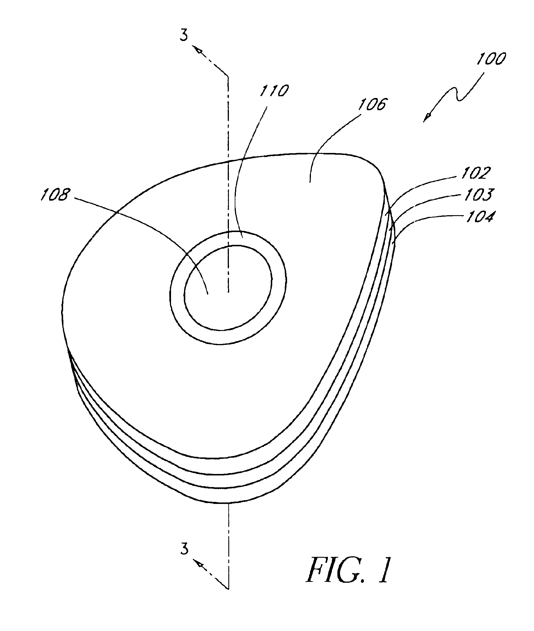
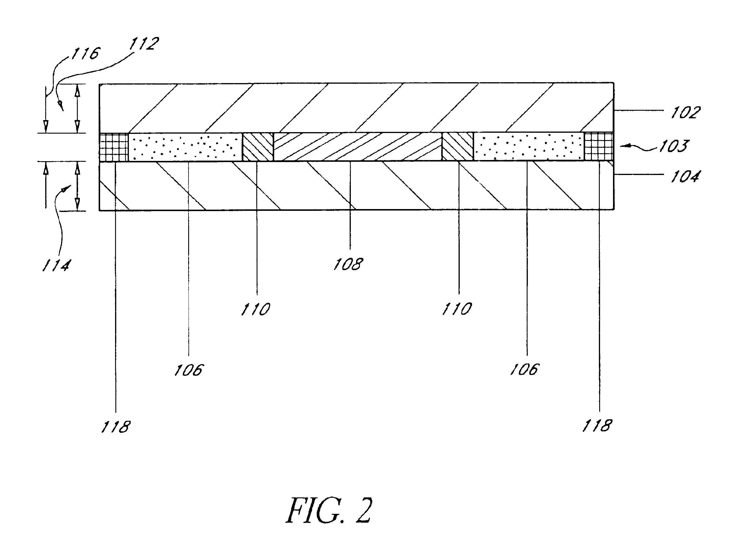
Referring initially to FIG. 1, a lens assembly that incorporates a supervision zone is shown and generally designated 100. FIG. 1 shows that the lens assembly 100 includes an upper lens 102, a variable index layer 103, and a lower lens 104. In a preferred embodiment, the variable index layer is made of ultra-violet curing epoxy which exhibits an index of refraction that can be changed by exposure to ultraviolet radiation. However, it is to be appreciated that other materials which exhibit similar characteristics, namely a variable index of refraction, may be incorporated into the present invention without departing from the spirit of the invention.

The variable index layer 103 makes up the normal vision zone 106, the transition zone 110, and the supervision zone 108, where the epoxy at each zone is cured to a specific index of refraction. The normal vision zone 106 corrects the lower order spherical and cylindrical aberrations of the patient's eye. The transition zone 110 allows for ...


PUM

PropertyMeasurementUnit
diameteraaaaaaaaaa
sizeaaaaaaaaaa
constant index of refractionaaaaaaaaaa

Abstract

An Eyeglass Manufacturing Method Using Epoxy Aberrator includes two lenses with a variable index material, such as epoxy, sandwiched in between. The epoxy is then cured to different indexes of refraction that provide precise corrections for the patient's wavefront aberrations. The present invention further provides a method to produce an eyeglass that corrects higher order aberrations, such as those that occur when retinal tissue is damaged due to glaucoma or macular degeneration. The manufacturing method allows for many different applications including, but not limited to, supervision and transition lenses.

Description

The present invention relates generally to an eyeglass manufacturing method using a layer with a variable index of refraction. More specifically, the present invention pertains to patient-specific spectacle lenses manufactured with an variable index aberrator in order to more accurately correct lower order aberrations and additionally correct higher order aberrations. The present invention also provides a means for correcting vision problems caused by retinal dysfunction.Present manufacturing techniques for eyeglass lenses are capable of producing lenses that correct only the lower order (sphere and cylinder) aberrations. Customarily, lens blanks are available in discrete steps of refractive power of 0.25 diopters. In most cases, these steps are too large to create optimum vision for a patient's eye.Current manufacturing techniques do not effectively treat vision problems resulting from retinal dysfunction. For example, in macular degeneration, patients suffer from vision loss in se...

Claims


Application Information

Patent Timeline
Patent Type & Authority Patents(United States)
IPC IPC(8): B29D11/00G02C7/02G02B27/00G02B3/00A61F9/00G02C7/06B29K663/00
CPCB29D11/0073G02B3/0087G02B27/0025G02C7/02G02C7/027G02C7/028G02C7/06G02C7/061G02C2202/10G02C2202/12G02C2202/14G02C2202/16G02C2202/22B29D11/00355
Inventor DREHER, ANDREAS W.
Owner ESSILOR INT CIE GEN DOPTIQUE
Why Eureka
Try Eureka