Optical fiber having a low-shrink buffer layer and methods of manufacturing the same

a buffer layer and optical fiber technology, applied in the field of optical fibers, can solve the problems of shrinkage of buffering materials, weaker optical signals, and loss of insertions in fiber-to-fiber separation

Inactive Publication Date: 2004-03-30
CORNING OPTICAL COMM LLC
View PDF38 Cites 25 Cited by
  • Summary
  • Abstract
  • Description
  • Claims
  • Application Information

AI Technical Summary

Problems solved by technology

In general, insertion loss results in a weaker optical signal and is therefore undesirable.
Fiber-to-fiber separation also implies an insertion loss due to Fresnel reflections at one of the two glass end interfaces.
When the buffering material such as a polyvinyl chloride (PVC) cools, shrinkage of the buffering material can occur.
Shrinkage of the buffer layer can result in undesirable compressive axial stress that can cause undesirably high strains in the optical fiber, which in turn can cause undesirable optical performance degradation.
Additionally, there are other sources of buffer layer shrinkage that may cause degradation in optical performance.
Such variations can result in, for example, buffer layer expansion and contraction.
The expansion and contraction of the buffer layer can cause tensile and compressive forces to be transferred to the optical fiber(s) within the interconnect assembly, thereby resulting in undesired optical degradation in the interconnect assembly.

Method used


Image

  • Optical fiber having a low-shrink buffer layer and methods of manufacturing the same
  • Optical fiber having a low-shrink buffer layer and methods of manufacturing the same
  • Optical fiber having a low-shrink buffer layer and methods of manufacturing the same

Examples


Embodiment Construction

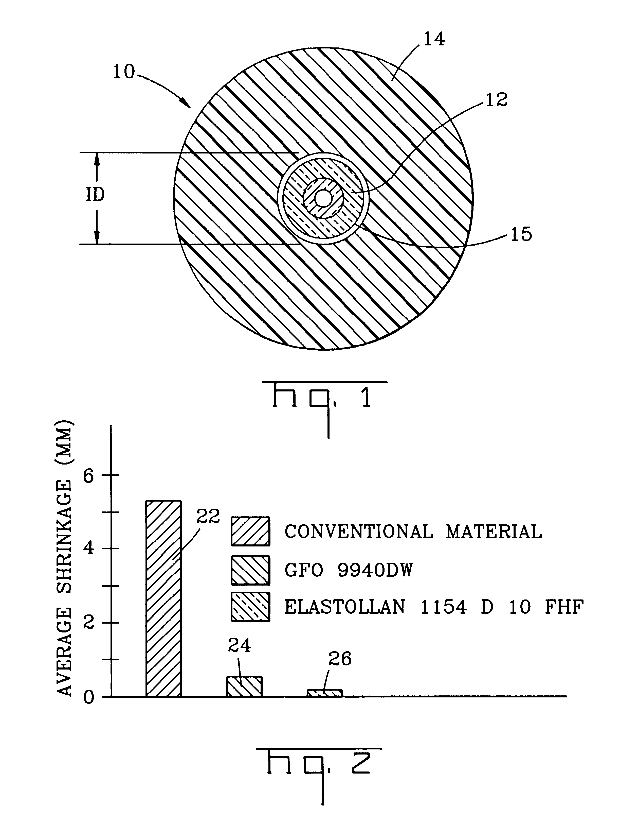
Referring to FIG. 1, the present inventions will be described with reference to an exemplary buffered optical fiber 10. Buffered optical fiber 10 includes at least one optical fiber 12 having at least one buffer layer 14 therearound. Buffer layer 14 according to the present inventions includes a low-shrink characteristic that preserves optical performance, for example, during temperature variations and / or high humidity environments. A portion of buffer layer 14 can be in contact with the coating on optical fiber 10; however, in other embodiments a suitable substance, for example, interfacial layer 15 can be interposed between buffer layer 14 and an outer coating of optical fiber 12. If used, interfacial layer 15 is generally interposed between optical fiber 12 and buffer layer 14 to promote, for example, size control and / or stripability of buffer layer 14. However, stripability of buffered optical fiber 10 of the present inventions can be achieved when interfacial layer 15 is not pr...


PUM

PropertyMeasurementUnit
strip forceaaaaaaaaaa
temperatureaaaaaaaaaa

Abstract

At least one buffered optical fiber, and methods for manufacturing the same, including an optical fiber and a buffer layer. The buffer layer generally surrounds the optical fiber and has a low-shrink characteristic that preserves optical performance during, for example, temperature variations. In other embodiments, the at least one buffered optical fiber may be a fiber optic ribbon.

Description

FIELD OF THE INVENTIONSThe present inventions relate to optical fibers and, more particularly, to optical fibers having at least one buffer layer.BACKGROUND OF THE INVENTIONSOptical fibers are used to transmit information signals, for example, voice, video, and / or data information. Optical fibers are relatively fragile silica-based filament-like strands and require protection to preserve the optical performance thereof. For example, optical fibers require protection from macro-bending and / or micro-bending to inhibit undesired optical performance degradation.In order to meet these requirements, optical fibers may include a protective layer therearound. For example, an optical fiber can have a buffer layer therearound to protect the optical fiber during bending. The buffer layer may be either loosely or tightly disposed around the optical fiber. A loose buffered optical fiber generally has a relatively small gap between the optical fiber and the buffer layer, for example, a gap of abo...

Claims


Application Information

Patent Timeline
Patent Type & Authority Patents(United States)
IPC IPC(8): G02B6/44
CPCG02B6/443G02B6/4486G02B6/4403G02B6/4495G02B6/4431
Inventor LANIER, JENNIFER K.PATEL, NAREN I.HALL, DONALD K.REGISTER, III, JAMES A.RUTTERMAN, DANIEL J.
Owner CORNING OPTICAL COMM LLC
Why Eureka
Try Eureka