Automatic fuel system cleaner

a fuel system and automatic technology, applied in the direction of cleaning using liquids, instruments, packaged goods, etc., can solve the problems of fuel injectors, fuel rail components, and intake manifold cavities becoming clogged and operating inefficiently, affecting fuel efficiency and engine performance, and clogging orifices and critical fuel combustion pathways,

Inactive Publication Date: 2004-04-06
CPS PROD CANADA
View PDF7 Cites 96 Cited by
  • Summary
  • Abstract
  • Description
  • Claims
  • Application Information

AI Technical Summary

Problems solved by technology

Fuel injectors, fuel rail components, and intake manifold cavities become clogged and operate inefficiently due to the normal accumulation of carbon and petroleum varnish byproducts.
The deposits tend to accumulate and clog orifices and critical fuel combustion pathways and conduits, including fuel rail assemblies and fuel injectors that carry the atomized fuel mixture into the combustion chamber.
If the nozzles and related components operate ineffectively or fuel nozzle spray patterns are altered due to carbon or contaminates, fuel efficiency an...

Method used


Image

  • Automatic fuel system cleaner
  • Automatic fuel system cleaner
  • Automatic fuel system cleaner

Examples


Embodiment Construction

The present invention may be described herein in terms of functional block components and various processing steps. It should be appreciated that such functional blocks may be realized by any number of hardware components configured to perform the specified functions. It should be further appreciated that the particular implementations shown and described herein are merely exemplary and are not intended to limit the scope of the present invention in any way.

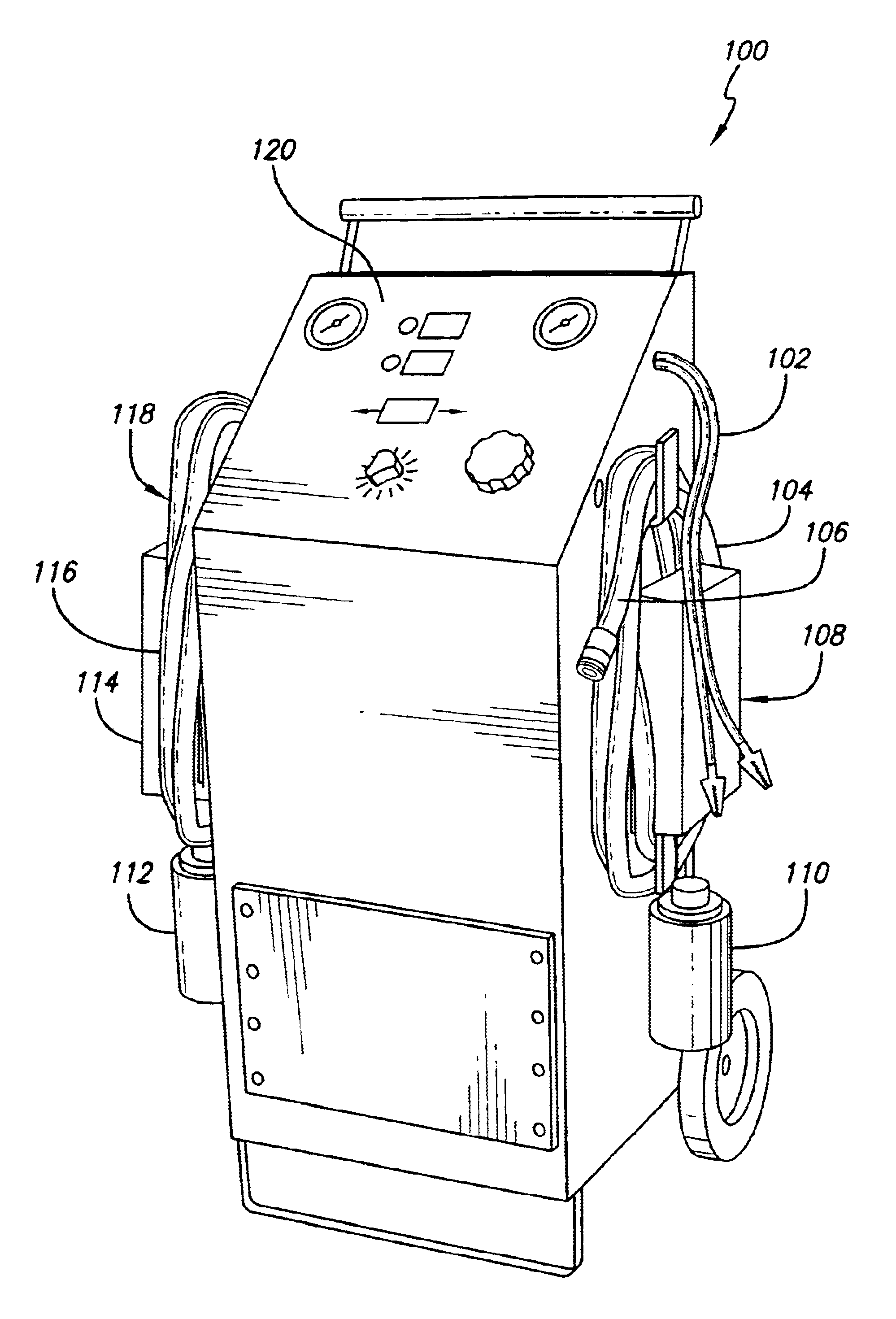
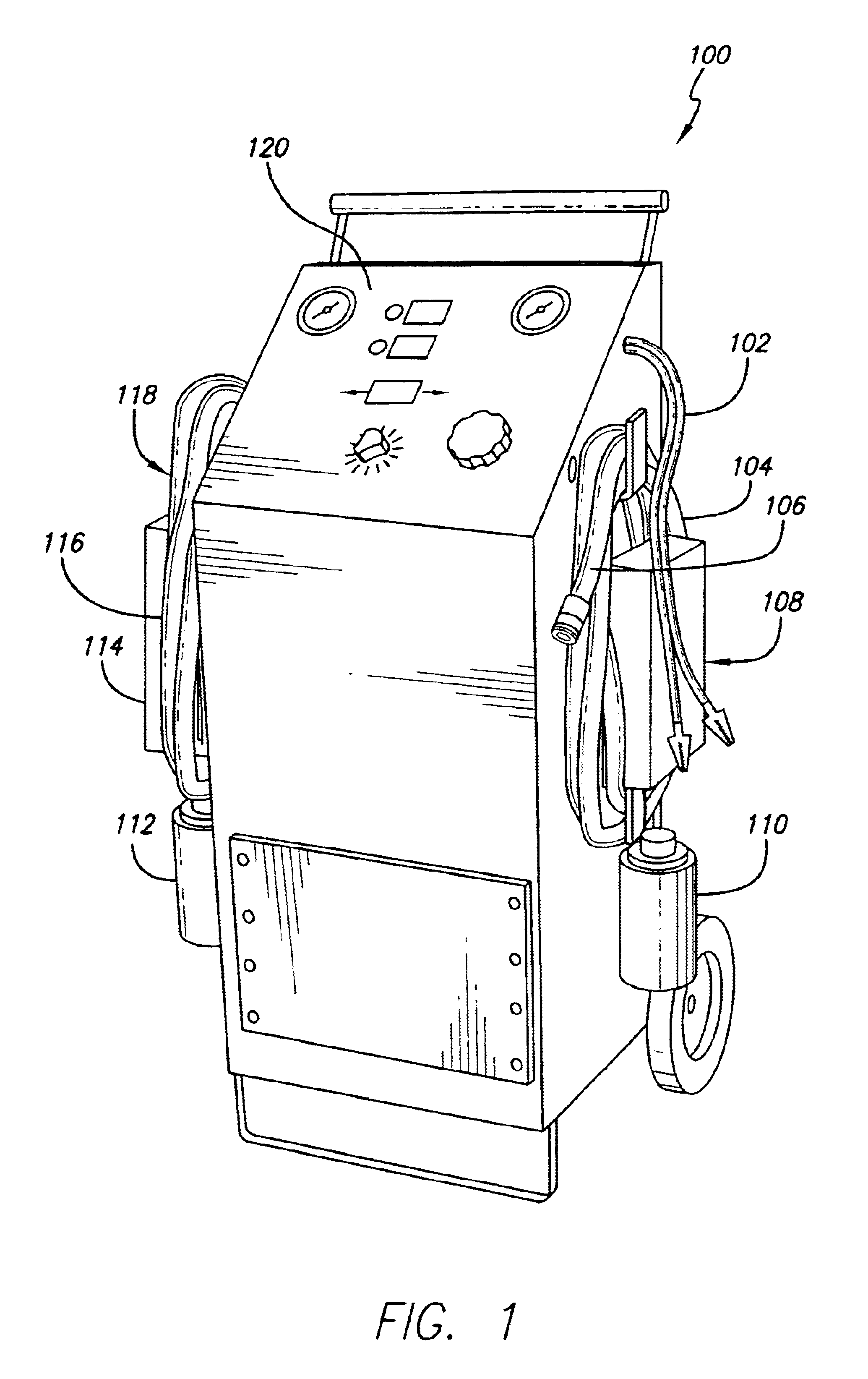
FIG. 1 shows an automatic fuel system cleaner according to one embodiment of the present invention. As shown in FIG. 1, automatic fuel system cleaner 100 includes power harness 102, which supplies power to automatic fuel system cleaner 100 by connecting to a power source, such as a 12.0 vdc vehicle battery (not shown in FIG. 1). Power harness 102 comprises positive and negative power cables, respectively, that can connect to positive and negative terminals of the power source (not shown in FIG. 1). Automatic fuel system cleaner 1...


PUM

PropertyMeasurementUnit
Pressureaaaaaaaaaa

Abstract

An apparatus and method for cleaning either a diesel or a gasoline fuel system. The automatic fuel cleaner apparatus comprises a diesel service portion and a gasoline service portion. The diesel and gasoline service portions each includes a return hose having a first end capable of being coupled to a fuel line outlet of the fuel system. Each service portion further includes a detergent reservoir having an input connected to the return hose. Each service portion also includes a pump having an input connected to an output of the detergent reservoir. The diesel and gasoline service portions each further includes an output hose having a first end connected to a pump output and a second end capable of being coupled to a fuel line inlet. The gasoline service portion also comprises a pressure regulator connected to the output of the gasoline pump.

Description

1. Field of the InventionThe present invention relates generally to servicing fuel systems. More particularly, the present invention relates to method and apparatus for cleaning vehicle engine fuel systems.2. Related ArtOne area of vehicular maintenance concerns the removing and cleaning of carbon deposits from gas and diesel internal combustion engine fuel systems. Fuel injectors, fuel rail components, and intake manifold cavities become clogged and operate inefficiently due to the normal accumulation of carbon and petroleum varnish byproducts. The deposits tend to accumulate and clog orifices and critical fuel combustion pathways and conduits, including fuel rail assemblies and fuel injectors that carry the atomized fuel mixture into the combustion chamber. If the nozzles and related components operate ineffectively or fuel nozzle spray patterns are altered due to carbon or contaminates, fuel efficiency and engine performance decrease and emissions levels become excessive.The conv...

Claims


Application Information

Patent Timeline
IPC IPC(8): F02M65/00F02B77/04
CPCF02B77/04F02M65/007
Inventor ROME, JOHN A.KAVADELES, BILLOREJEL, JESUS G.
Owner CPS PROD CANADA
Why Eureka
Try Eureka