Manually operable trigger sprayer with rearwardly located sprayer valve

a sprayer valve and manually operable technology, applied in the direction of burners, combustion types, combustion processes, etc., can solve the problems of foaming of liquid dispensed and turbulence created

Inactive Publication Date: 2004-04-06
WESTROCK DISPENSING SYST
View PDF4 Cites 27 Cited by
  • Summary
  • Abstract
  • Description
  • Claims
  • Application Information

AI Technical Summary

Benefits of technology

The present invention also provides a telescoping foamer nozzle that has a relatively small number of component parts resulting in reliable long-term operation.
The present invention also provides a telescoping nozzle that has a relatively small number of component parts which can be manufactured easily in volume resulting in a relatively low unit cost.
The present invention also provides a valve that controls the flow of liquid in a downstream direction from a pump of the trigger sprayer to a nozzle exit port of the trigger sprayer where the valve is constructed to be easily assembled into the trigger sprayer.
The present invention also provides a sprayer housing construction with a liquid discharge passage that is easily assessable through a liquid discharge opening in the sprayer housing that communicates with the liquid discharge passage for assembly of the valve of the invention into the liquid discharge passage.
The present invention also provides the valve with an extended stem or shaft that has a length that extends the shaft beyond the liquid discharge passage opening of the sprayer housing when the valve is assembled into the liquid discharge passage, facilitating the assembly of the valve into the liquid discharge passage.

Problems solved by technology

By controlling the amount of peripheral flow of the liquid impinged upon by the interrupter in the stream periphery, turbulence is created in the liquid with consequent pressure drop and ingress of counter-flowing ambient air which mixes with the liquid and causes foaming of the liquid dispensed by the sprayer.

Method used


Image

  • Manually operable trigger sprayer with rearwardly located sprayer valve
  • Manually operable trigger sprayer with rearwardly located sprayer valve
  • Manually operable trigger sprayer with rearwardly located sprayer valve

Examples


Embodiment Construction

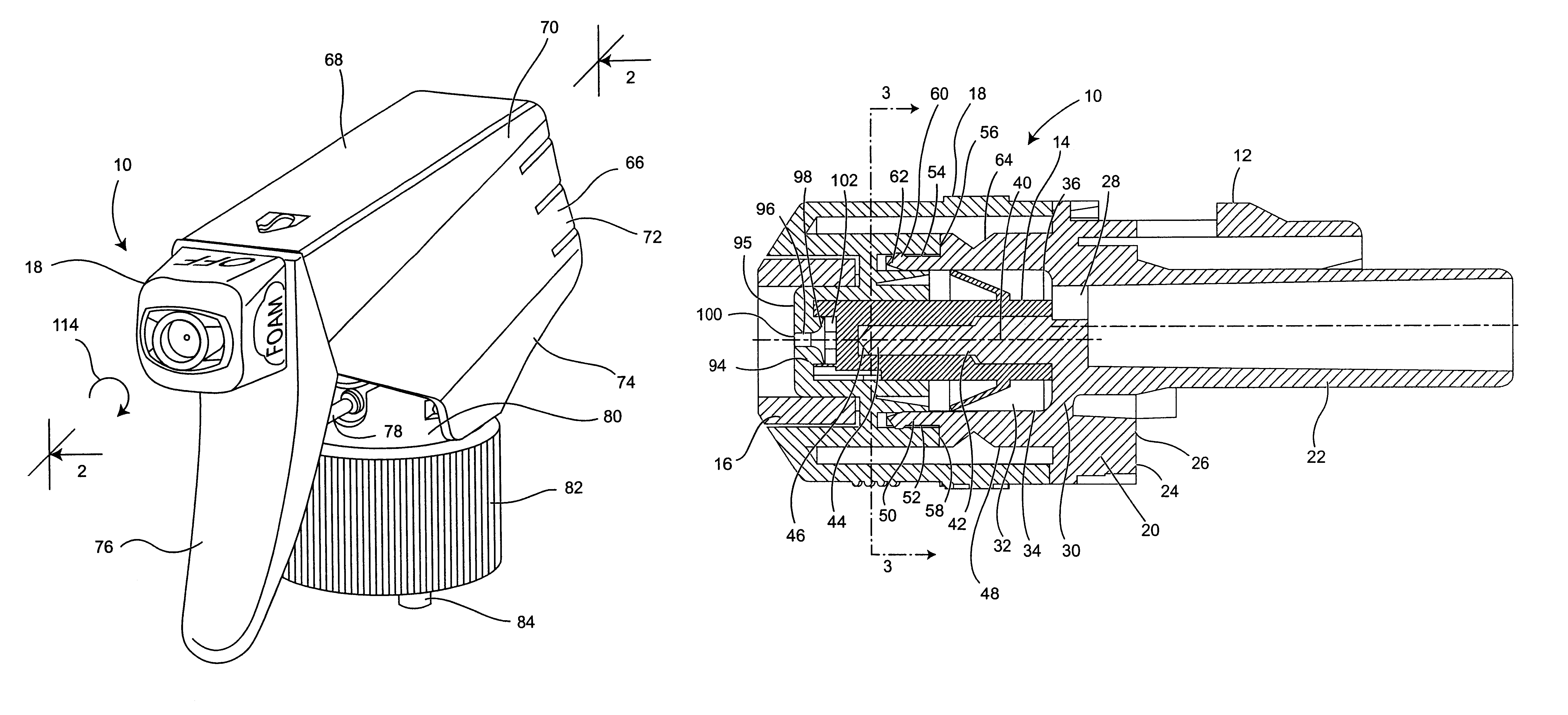
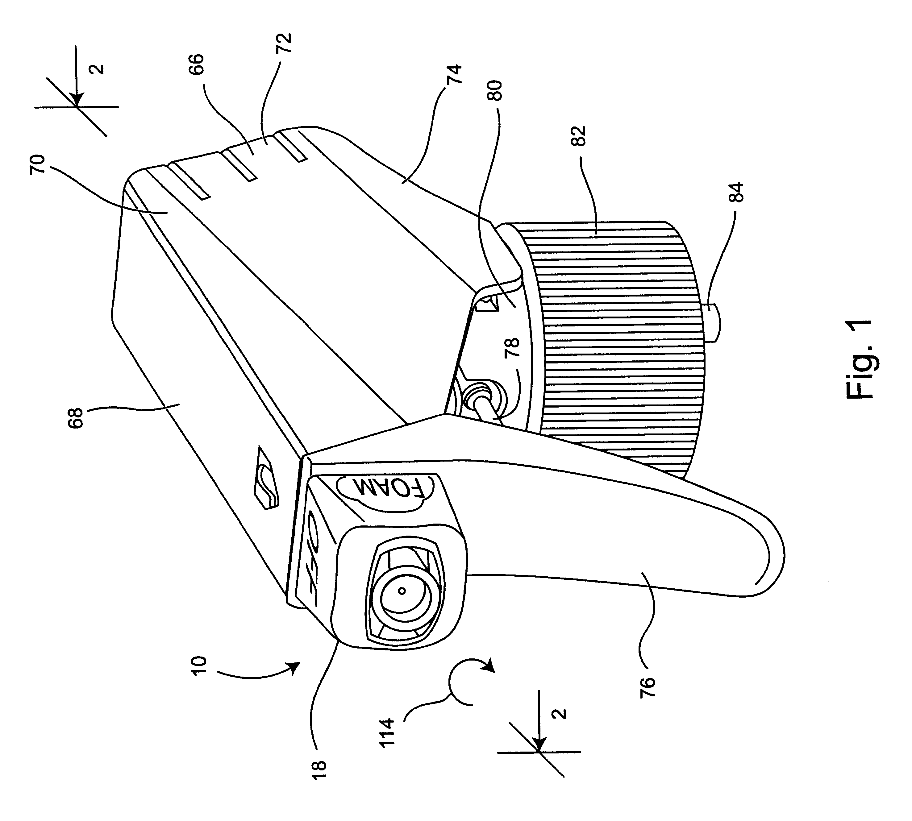
With reference to the drawings, in which like reference numbers designate like or corresponding parts throughout, there is shown in FIGS. 1 and 2 a telescoping foamer nozzle generally designated by the reference number 10, made in accordance with the present invention, which includes a nozzle member 12, a liquid spinner member 14, a foamer tube 16 and cap member 18.

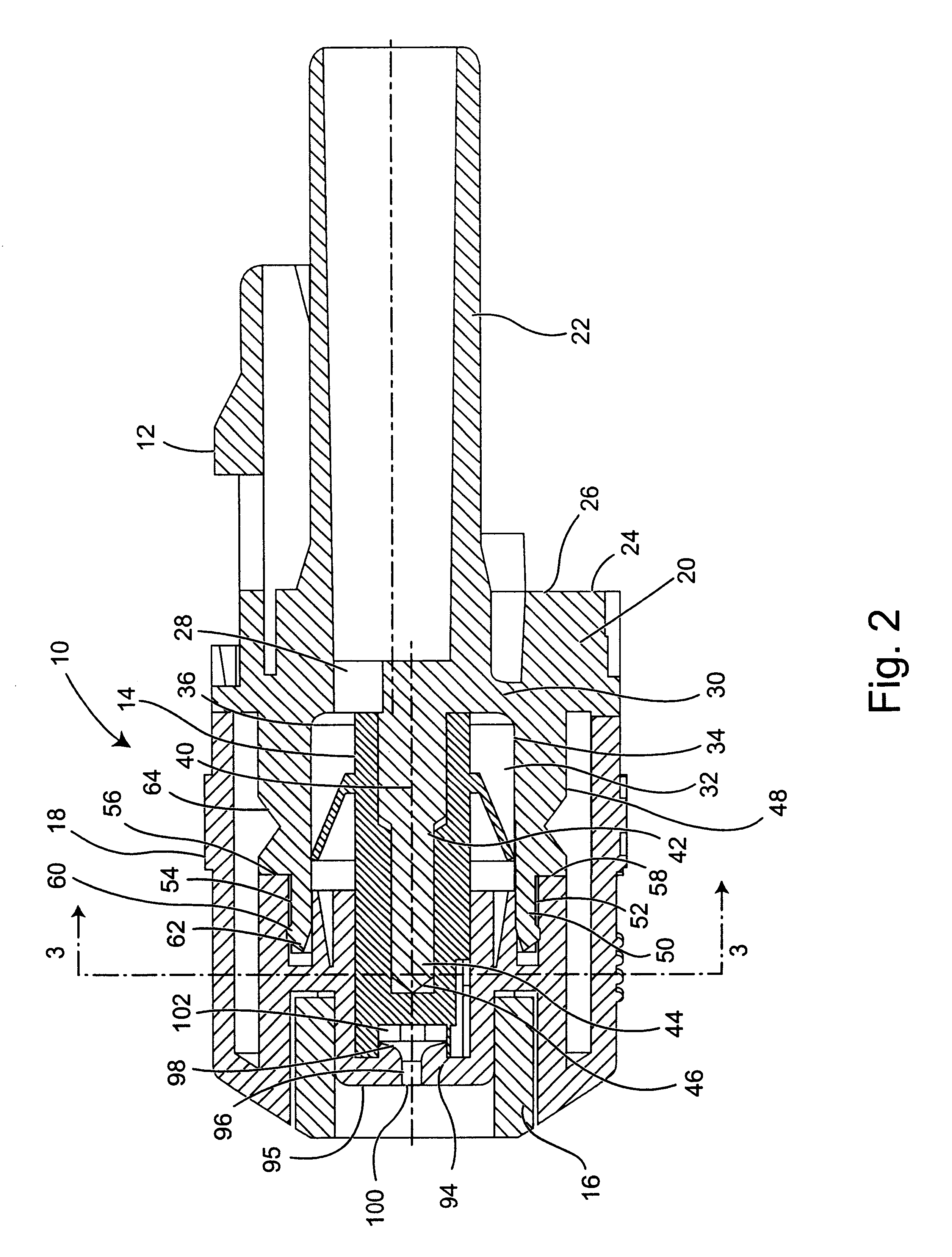
As shown in FIG. 2, the nozzle member 12 is an intricately formed component which includes a central portion 20 and a centrally disposed feed tube 22 which projects from a rear surface 24 of the central portion. The feed tube 22 communicates via a port 28 formed in a center wall 30 of the central portion 20 with a cavity 32 on the opposite side of the central wall 30 from the feed tube 22. The cavity 32 is defined by a cylindrical wall having lower 34 and upper 36 interior surfaces that project from the center wall 30.

A shaft 40 projects from the center wall 30. The shaft 40 is centrally located with respect to the interi...


PUM


Abstract

A trigger sprayer valve assembly that has a conical flange that controls the flow of liquid in a downstream direction through a liquid passage of the trigger sprayer. The valve is constructed with an elongate stem or shaft that facilities the assembly of the valve into the trigger sprayer and a positioning plug that solely holds the valve in a centered position in the liquid passage of the trigger sprayer.

Description

(1) Field of the InventionThe present invention pertains to a valve of a manually operable trigger sprayer. In particular, the present invention pertains to a trigger sprayer valve positioned in a liquid passage communicating the pump of the sprayer with the nozzle exit port of the sprayer where the valve is constructed with a flexible, conical flange that controls the flow of liquid through the trigger sprayer in the downstream direction while preventing return, upstream liquid flow. In addition, the valve is constructed with an extended shaft projecting from the conical flange that facilitates the assembly of the valve into the sprayer housing of the trigger sprayer.(2) Description of the Related ArtThe prior art related to atomizers and trigger sprayers includes the following U.S. Patents.U.S. Pat. No. 1,900,087 to Aronson teaches an atomizer in which the operating elements are locked when the device is not in use, thereby preventing objectionable unintentional discharge of the c...

Claims


Application Information

Patent Timeline
Patent Type & Authority Patents(United States)
IPC IPC(8): B05B7/00B05B11/00B05B1/34B05B1/02
CPCB05B1/3468B05B7/005B05B11/0029B05B1/3421B05B11/0062B05B11/3057B05B11/1057
Inventor FOSTER, DONALD D.NELSON, PHILIP L.
Owner WESTROCK DISPENSING SYST
Why Eureka
Try Eureka