
Land grid array connector assembly having a stiffener with pivot bores

a technology of connector assembly and pivot bore, which is applied in the direction of coupling device connection, electrical apparatus construction details, engagement/disengagement of coupling parts, etc., can solve the problem of affecting the electrical connection between the cpu and the pcb

Inactive Publication Date: 2004-04-06
HON HAI PRECISION IND CO LTD
View PDF25 Cites 23 Cited by
  • Summary
  • Abstract
  • Description
  • Claims
  • Application Information

AI Technical Summary

Benefits of technology

Another object of the present invention is to provide an LGA connector assembly which has a lever mechanism configured to minimize the risk of the lever breaking out from the LGA connector assembly in use.
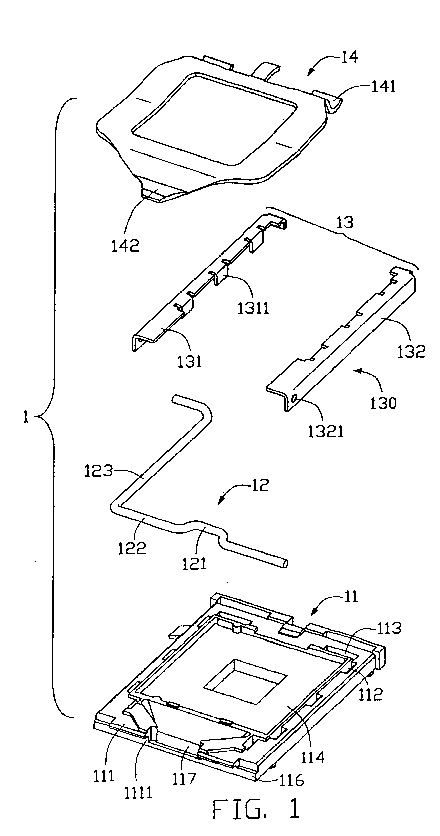
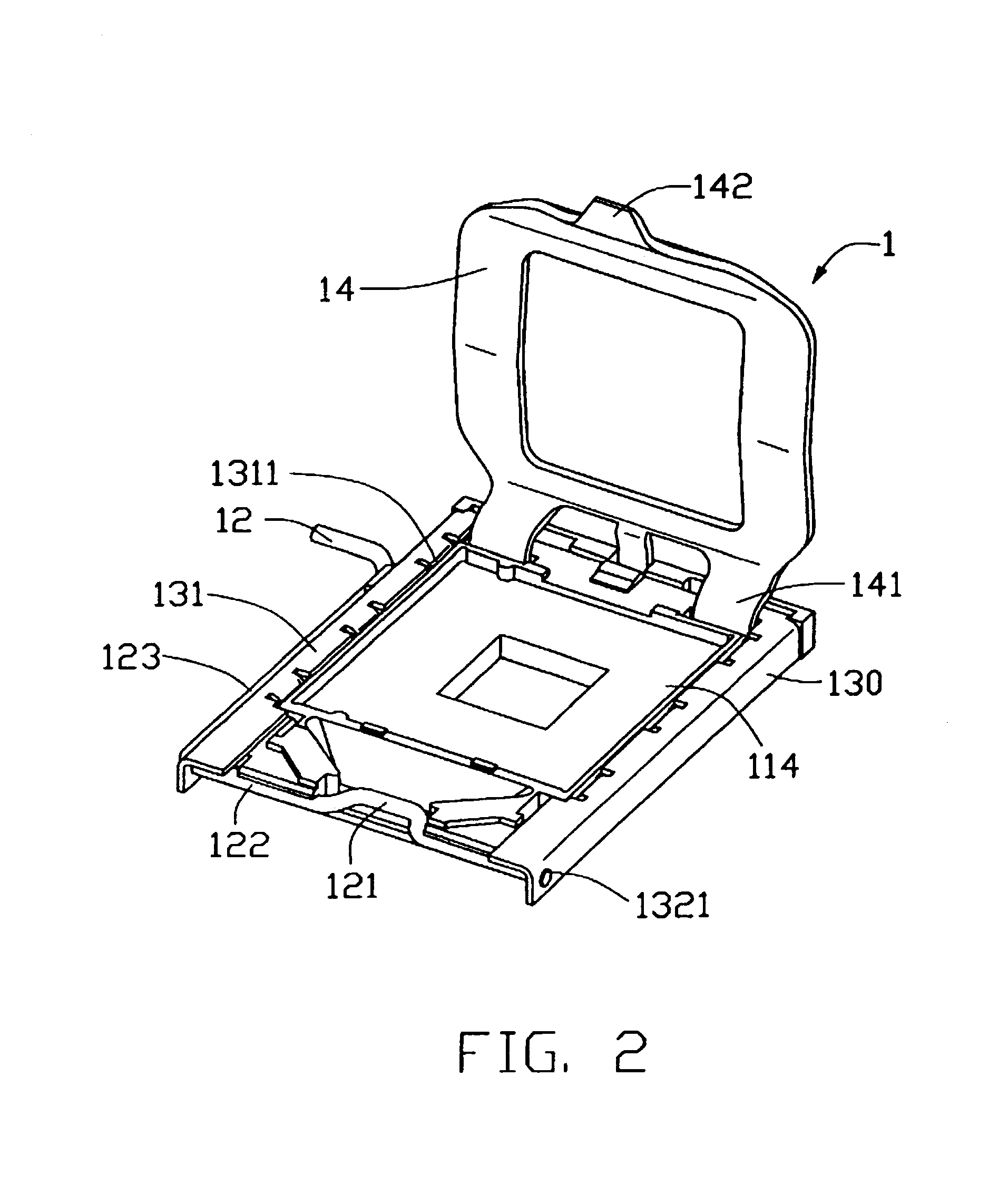
To achieve the above-mentioned objects, an LGA connector assembly in accordance with a preferred embodiment of the present invention comprises an insulative base, a stiffener mounted to the base, a lever pivotally mounted to one end of the base, and a metal clip pivotally mounted to an opposite end of the base for engaging with the lever. The base defines a rectangular cavity in a middle thereof and a plurality of rectangular holes in two opposite lateral sides thereof. The base has a forewall at an end thereof. The stiffener comprises a pair of metal reinforcing members covering the opposite lateral sides of the base. Each reinforcing member comprises a top portion, a flange depending perpendicularly from an outside edge of the top portion, and three projecting portion depending perpendicularly from an opposite inner edge of the top portion for engaging with the holes of the base. When the reinforcing members are mounted to the base, the ends of the flanges and the forewall of the base cooperatively define a channel. Each of the flanges defines a pivot bore at an end of the channel. The lever is received in the channel with pivoting in the pivot bores of the reinforcing members. Thus, when the lever and the clip are rotated to tightly attach a CPU in the LGA connector assembly, the base is able to withstand forces from the clip without any deformation and warpage, and the lever is reliably retained in the channel with minimal risk of breaking out from the channel.

Problems solved by technology

When deformation or warpage occurs, some contacts cannot firmly contact the metallic contact pads of the CPU, which disrupts the electrical connection between the CPU and the PCB.

Method used


Image

  • Land grid array connector assembly having a stiffener with pivot bores
  • Land grid array connector assembly having a stiffener with pivot bores
  • Land grid array connector assembly having a stiffener with pivot bores

Examples


Embodiment Construction

Reference will now be made to the drawings to describe the present invention in detail.

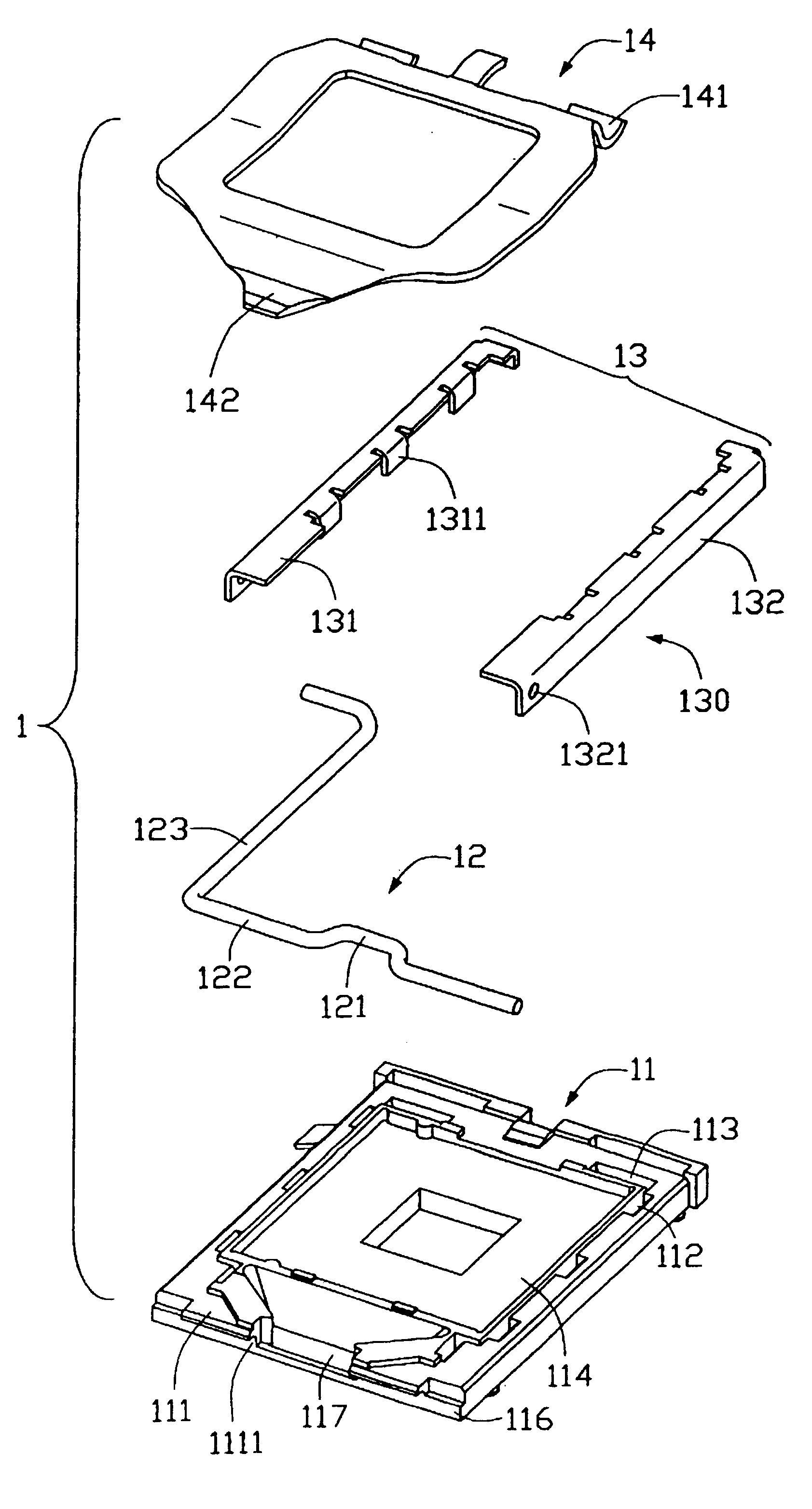
Referring to FIG. 1, an LGA connector assembly 1 in accordance with the preferred embodiment of the present invention is adapted for electrically connecting an electronic package, such as an LGA central processing unit (CPU) (not shown), with a circuit substrate, such as a printed circuit board (PCB) (not shown). The LGA connector assembly 1 comprises an insulative base 11 receiving a plurality of electrical contacts (not shown), a stiffener 13 mounted to the base 11, and a lever 12 and a metal clip 14 pivotally mounted to two opposite ends of the base 11 respectively.

The base 11 is substantially rectangular. The base 11 defines a pair of spaced, aligned slots 113 in one end thereof, a trapezoidal recess 117 in an opposite end thereof, and a rectangular cavity 114 between the slots 113 and the recess 117. The base 11 has a forewall 116. A pair of spaced upper ears 111 extends from an upper section...


PUM


Abstract

A land grid array (LGA) connector assembly (1) includes a base (11), a stiffener (13) mounted to the base, and a lever (12) and a metal clip (14) pivotally mounted to two opposite ends of the base and engaging with each other. The base has a forewall (116). The stiffener includes two flanges (132) covering two opposite lateral sides of the base. The ends of the flanges and the forewall of the base cooperatively define a channel. Each flange defines a pivot bore (1321) at an end of the channel. The lever is received in the channel, with pivoting in the pivot bores. Thus, when the lever are rotated to firmly attach a CPU in the LGA connector assembly, the base can withstand forces from the clip without any deformation and warpage, and the lever is reliably retained in the channel with minimal risk of breaking out from the channel.

Description

1. Field of the InventionThe present invention relates to land grid array (LGA) connector assemblies, and particularly to an LGA connector assembly adapted for receiving an LGA central processing unit (CPU) therein and electrically connecting the CPU with a printed circuit board (PCB).2. Description of the Prior ArtReferring to FIG. 3, a conventional LGA connector assembly 9 is adapted for electrically connecting an LGA CPU (not shown) having a multiplicity of metallic contact pads with a PCB (not shown). The LGA connector assembly 9 comprises an insulative base 91 receiving a plurality of electrical contacts (not shown), and a lever 92 and a metal clip 93 pivotally mounted to two opposite ends of the base 91 respectively.The lever 92 comprises a pair of locating portions 922, an offset securing portion 921 between the locating portions 922, and a handle portion 923 extending perpendicularly from an end of one of the locating portions 922. The clip 93 comprises a lip 931 at an end t...

Claims


Application Information

Patent Timeline
IPC IPC(8): H05K7/10
CPCH05K7/1007
Inventor MA, HAO-YUNSZU, MING-LUN
Owner HON HAI PRECISION IND CO LTD
Learn More