

Chassis with modular repositionable optical feedthrough plates
a technology of optical feedthrough plates and chassis, which is applied in the direction of domestic applications, cabinetry, support structure mounting, etc., can solve the problems of restricted location and orientation of most chassis designs, and achieve the effect of strong and durabl
- Summary
- Abstract
- Description
- Claims
- Application Information
AI Technical Summary
Benefits of technology
Problems solved by technology
Method used
Image

Examples
example 1
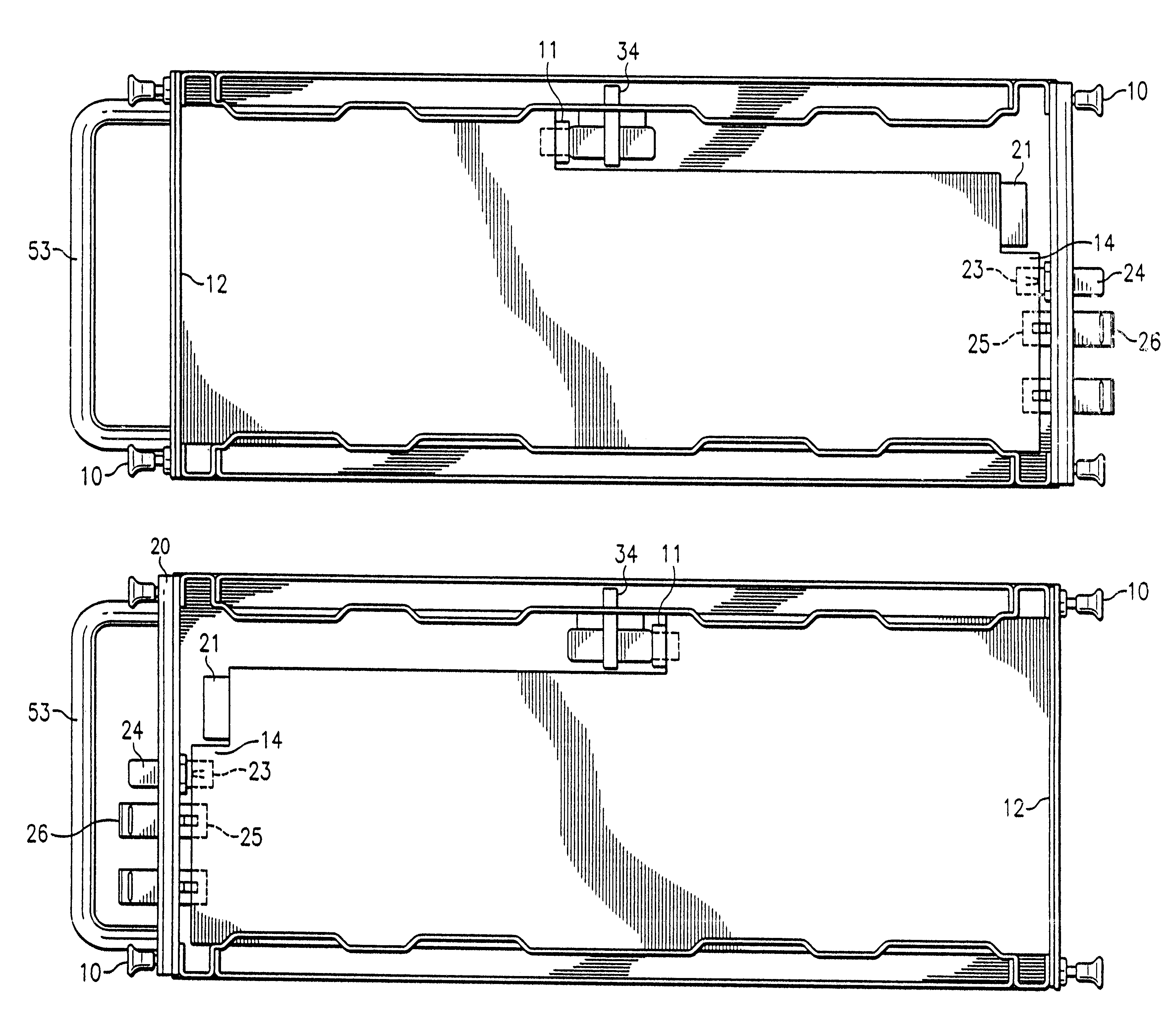
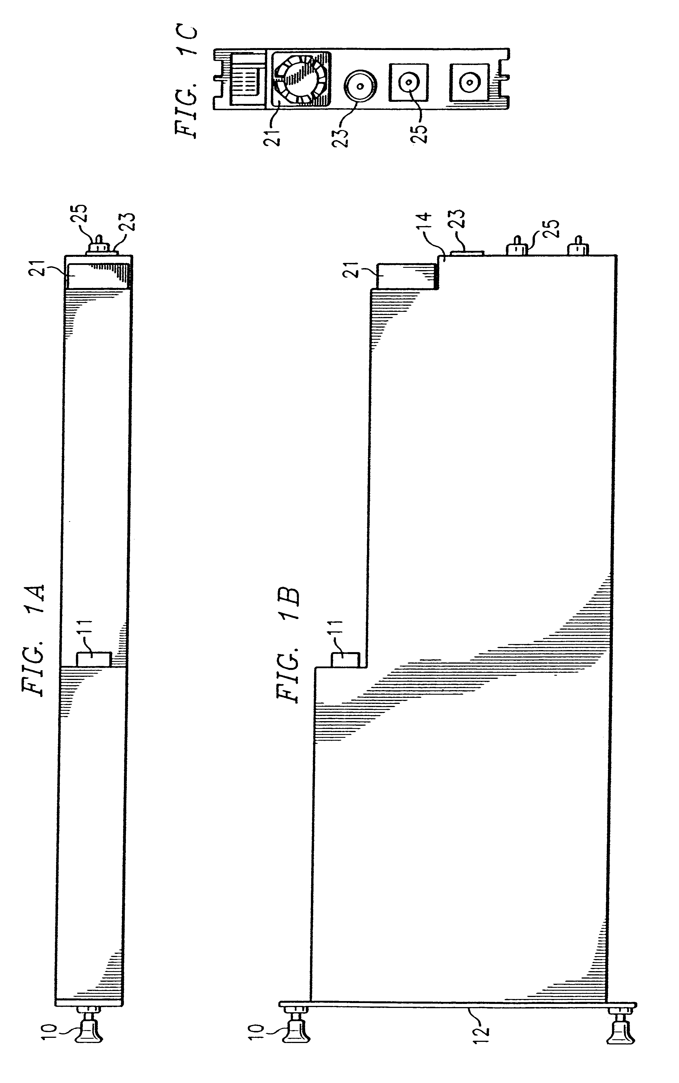
Referring to FIGS. 1A-1C, the module comprises at least one manually actuatable fastener 10 located at the closed end of the module 12 or the communicating end of the module 14. A power connector 11 is connected at the midpoint of the module. A fan 21, an RF connector 23, and at least one optical connector 25 are located at the communicating end of the module 14. A variety of other elements may also be located at the communicating end of the module 14. The power connector 11 can be located at various positions between the closed end 12 and the communicating end 14 of the module.
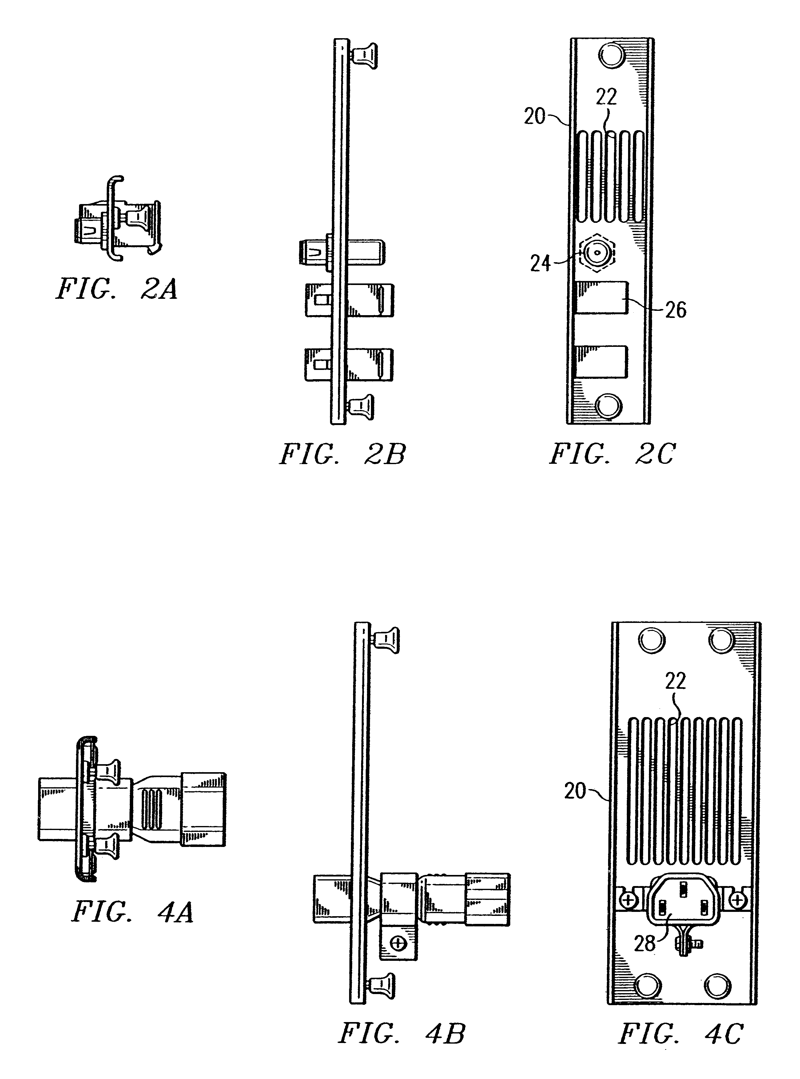
The repositionable plate 20 which is configured for connection to the module of FIGS. 1A-1C is depicted in FIGS. 2A-2C. The repositionable plate comprises manually actuatable fasteners 10, a plurality of ventilation slots 22 which can be operationally connected to the fan 21, an RF feed-through 24 which can be operationally connected to a RF connector 23, and at least one optical feed-through 26 each of which...
example 2
Referring to FIGS. 3A-3C, the power supply module comprises at least one manually actuatable fastener 10 located at the closed end of the module 12 or the communicating end of the module 14. A plurality of power connector 11 are connected at the midpoint of the module. A fan 21 and an AC inlet 27 are located at the communicating end of the module 14. A variety of other elements may also be located at the communicating end of the module 14. As in FIGS. 1A-1C, the power connector 11 can be located at various positions between the closed end 12 and the communicating end 14 of the module.
The repositionable plate 20 which is configured for connection to the module of FIGS. 3A-3C is depicted in FIGS. 4A-4C. The repositionable plate comprises manually actuatable fasteners 10, a plurality of ventilation slots 22 which can be operationally connected to a fan 21 and an electric feed-through 28 which can be operationally connected to an AC inlet 27. The repositionable plate 20 of FIGS. 4A-4C m...
example 3
Referring to FIGS. 5A-5C, a chassis is depicted comprising a plurality of module bay sections, including a plurality of module bay forward sections 30 and a plurality of module bay rearward sections 31. Repositionable plate mounting brackets 38 are connected to the chassis at the outside edge of each module bay forward sections 30 and module bay rearward sections 31. A plurality of connectors 36 are located between the forward and rearward module bay sections and are used for connection modules to the module bay sections 30-31. 16 modular bay sections are shown in FIGS. 5A-5C, any of which could be described as a first or second modular bay section. The location of the first and second modular bay sections within the chassis is not important to the invention. Card guides 45 are positioned near the bottom cover 51 of the chassis and are used for guiding modules into the module bay sections 30-31. On the exterior of the chassis optional cabinet mounts 52, handles 53 and a rack mount 5...
PUM
 Abstract
Description
Claims
Application Information