Device for positioning a wafer

Inactive Publication Date: 2004-04-13
ASM INTERNATIONAL
View PDF9 Cites 150 Cited by
  • Summary
  • Abstract
  • Description
  • Claims
  • Application Information

AI Technical Summary

Benefits of technology

Since the positioning-gas is in principle not involved in the treatment of the wafer, it is possible to select a much less expensive gas, such as nitrogen, for this positioning-gas. It is, however, desirable for the gas to be supplied at the same temperature as the actual process gas, in order in this way to eliminate the effects caused by temperature differences as far as possible.

Problems solved by technology

Although in the floating position the wafer is absolutely stable in the axial (vertical) direction, it has been found that the positioning in the radial (horizontal) direction provides problems: the wafer is able to move too easily in the radial direction.
However, this results in considerable pressure differences across the surface of the wafer, while a requirements for a uniform process result is that the range of pressure variation across the wafer is no greater than .+-.2.5%.

Method used


Image

  • Device for positioning a wafer
  • Device for positioning a wafer
  • Device for positioning a wafer

Examples


Embodiment Construction

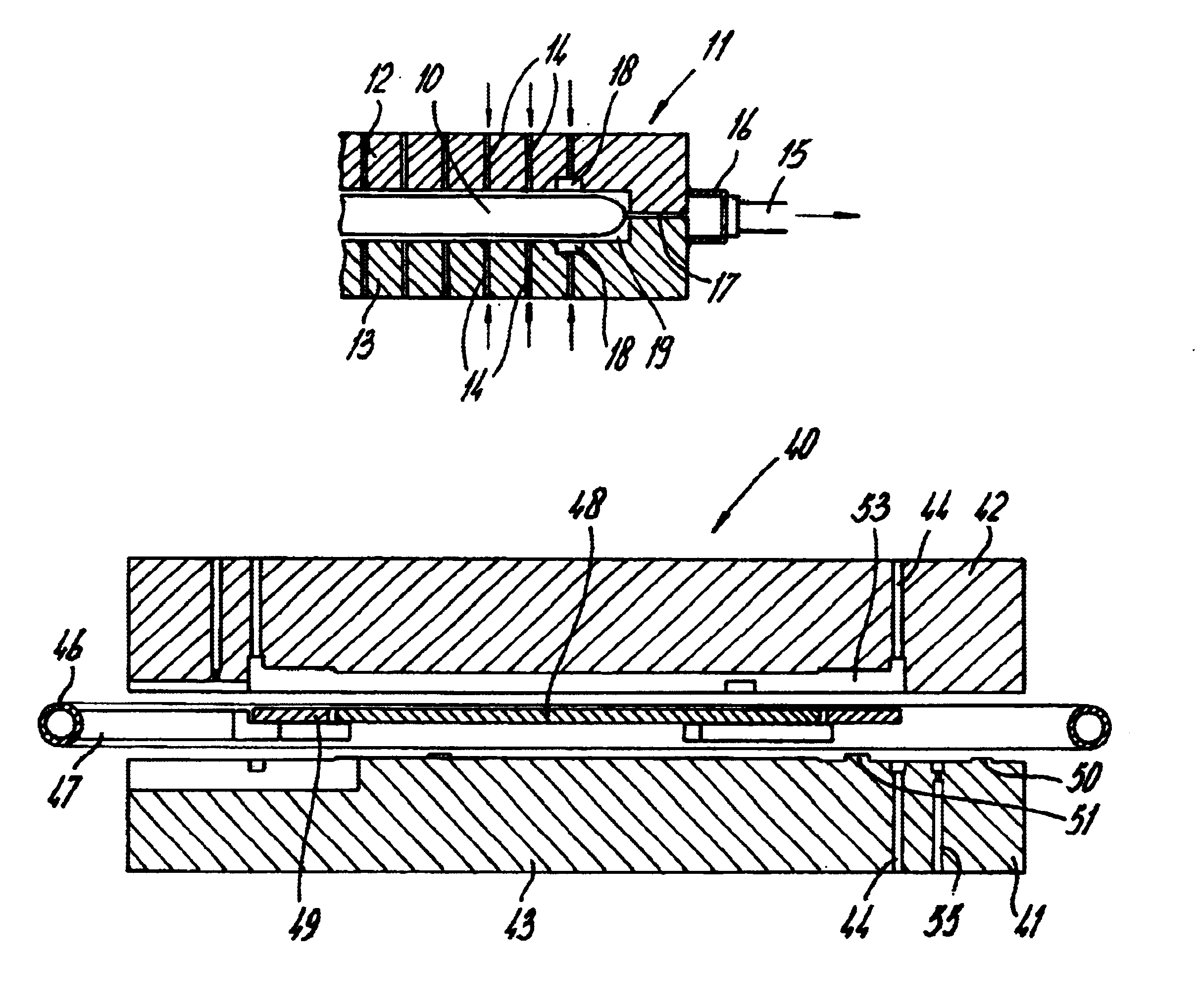
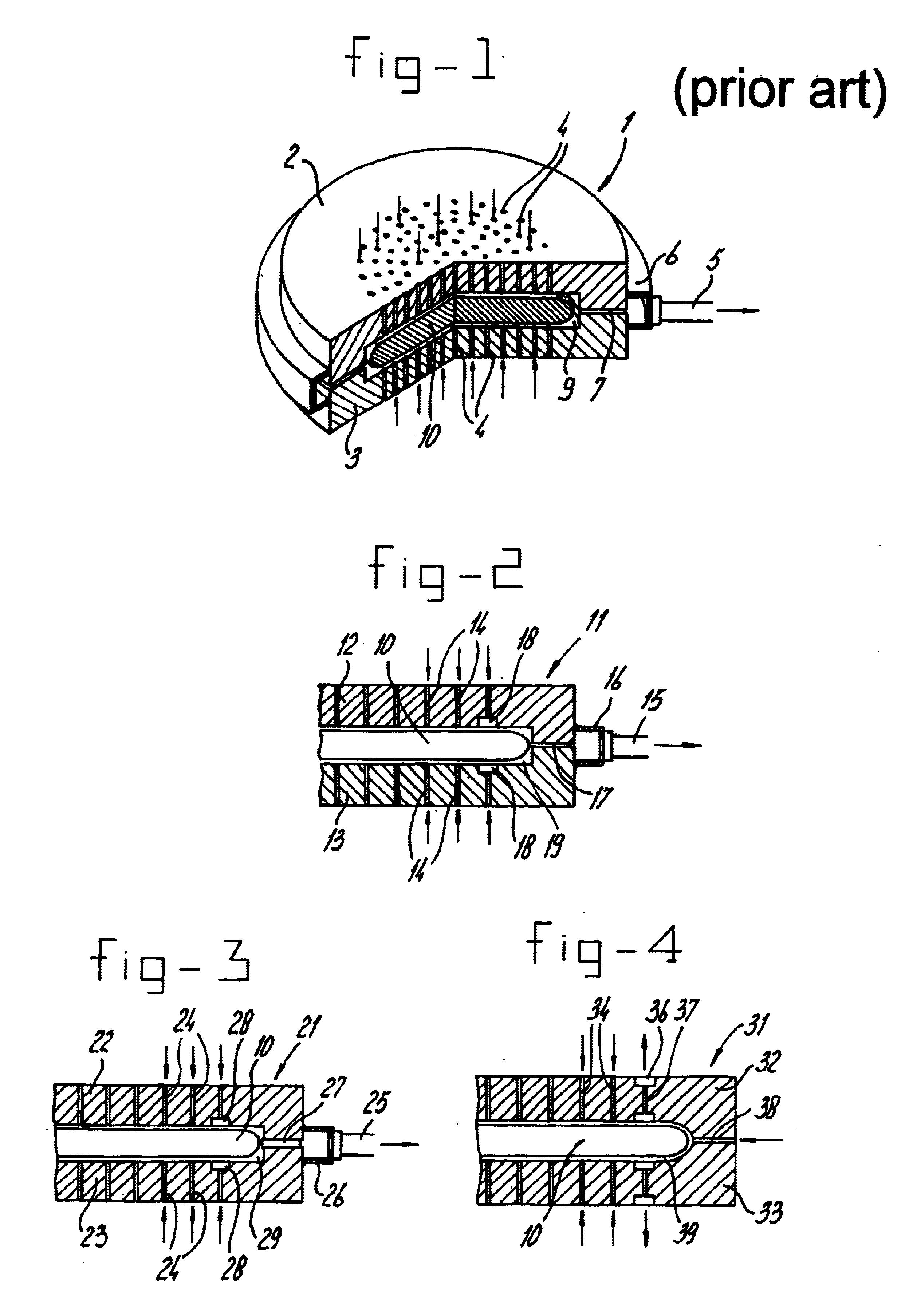
FIG. 1 shows a highly diagrammatic view of a device for the floating accommodation of a substrate or wafer. This device is denoted overall by 1 and comprises a chamber 9 which is delimited by a top part 2 and bottom part 3. Treatment-gas supply openings 4 are present in both the bottom part 3 and the top part 2. Gas is discharged through opening 7, which is annular, and this opening 7 is connected to an annular channel 6 which is connected to a discharge line 5. The wafer to be treated is denoted by 10. FIG. 1 does not show the heating means, which are preferably internal to each of the top part 2 and bottom part 3, nor does it show the structure for metering the gas through the openings 4. Accurate metering through each of the openings is of considerable importance in order to ensure that the wafer floats stably. The gas supplied on the one hand keeps the wafer in a floating position and on the other hand treats the wafer (chemically or physically). For a standard 200 mm wafer, the...


PUM


Abstract

Device for the floating accommodation of a wafer. This device comprises two mutually opposite parts which delimit a chamber in which the wafer is placed. By gas being supplied from opposite sides, the wafer is held in a floating position. To prevent the wafer from touching the lateral boundaries, it is proposed to provide a discharge of gas at least partially near the circumference of the chamber wherein the wafer is accommodated. This discharge is realised such that if the wafer moves from the intended position to such a gas discharge, by closing of said gas discharge, the pressure is locally increased such that a force is generated acting in opposite direction to return the wafer in the intended position.

Description

FIELD OF THE INVENTIONThe present invention relates generally to semiconductor processing, and more particularly to an apparatus and method for keeping a floating wafer centered within the apparatus.Dutch Patent 1003538 describes the individual treatment of wafers. A wafer is accommodated in a reactor, with the distance to the walls of the reactor being set to be comparatively small. It is thus possible for a particularly rapid hear transfer to take place. It is possible to heat the wafer to well above 1000.degree. C. within a few seconds. Since the wafer in principle does not have to be supported during this heating operation, but rather is held accurately in position by the gas streams, local temperature differences caused by mechanical contact are avoided. The very uniform heating of the wafer allows said short heating times to be achieved without the wafer becoming warped. Due to the high capacity of the reactor and the relatively low heat capacity of the wafer, in combination w...

Claims


Application Information

Patent Timeline
IPC IPC(8): H01L21/683H01L21/67H01L21/68
CPCH01L21/6838Y10S414/139H01L21/00
Inventor KUZNETSOV, VLADIMIR IVANOVICHRADELAAR, SIJBRANDVAN DER SANDEN, JACOBUS CORNELIS GERARDUSRUIJL, THEO ANJES MARIA
Owner ASM INTERNATIONAL
Why Eureka
Try Eureka