Light adjustable aberration conjugator

a conjugator and aberration technology, applied in the field of aberration correction in the optical system, can solve the problems of inconvenient operation, inconvenient use, and inability to adjust the light intensity,

Inactive Publication Date: 2004-04-13
RXSIGHT INC
View PDF22 Cites 68 Cited by
  • Summary
  • Abstract
  • Description
  • Claims
  • Application Information

AI Technical Summary

Problems solved by technology

This process can take hours in a production shop and days in a precision optical fabrication facility.
All of these approaches have drawbacks.
Virtually all of these methods are costly and time consuming.
Some are disadvantageous because of low efficiencies or because polarized light must be used.
Optical and optical system aberrations arise from fabrication, alignment, and residual design errors.

Method used


Image

  • Light adjustable aberration conjugator
  • Light adjustable aberration conjugator
  • Light adjustable aberration conjugator

Examples


Embodiment Construction

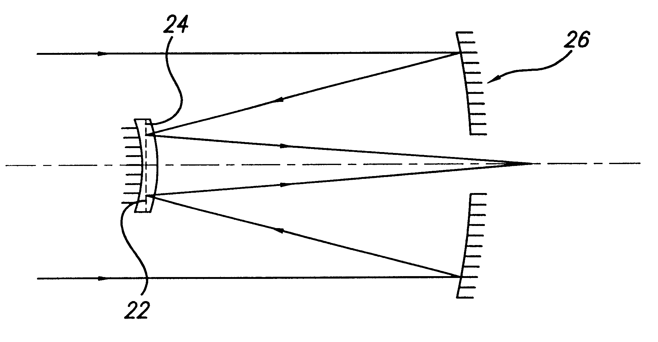
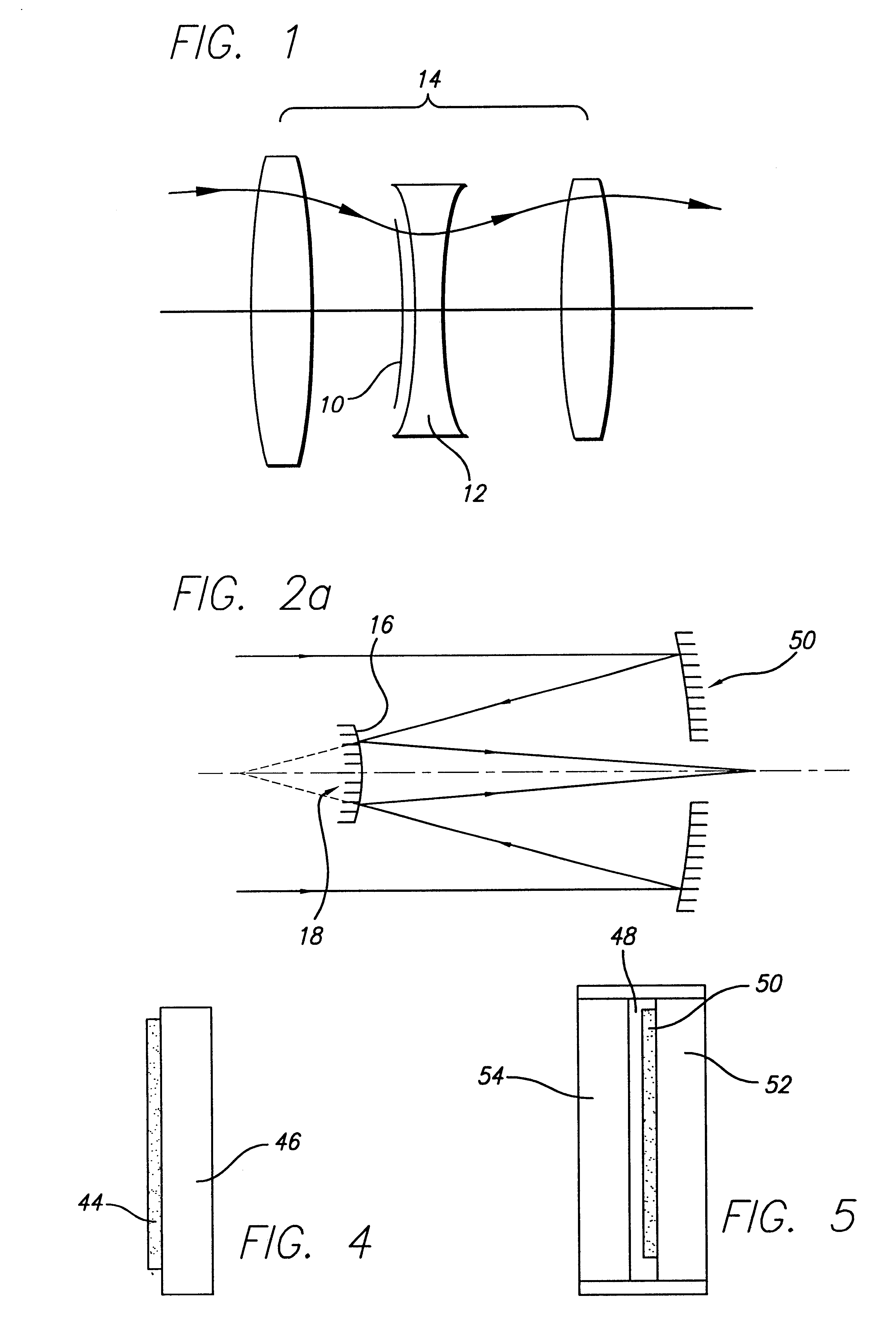
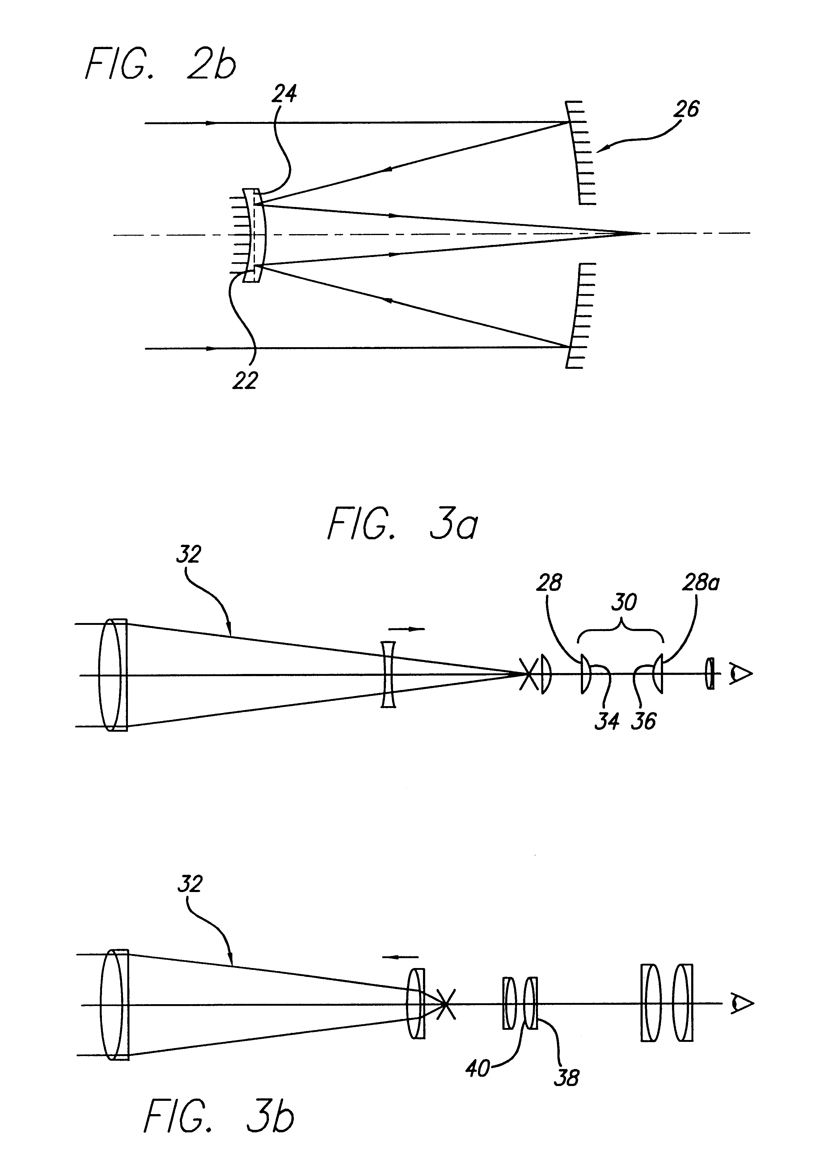
The purpose of this invention is to more easily correct the fixed aberrations in an optical system by placing the conjugate of the optical system aberrations on one of the surfaces in the optical system. Fixed, optical system aberrations include aberrations from fabrication, alignment, and residual design errors. Correcting the fixed aberrations with light rather than by polishing or by the use of deformable mirrors saves time and money. The invention has advantages over ion polishing, surface layered optical coatings and deposited masks, which have to be performed in a vacuum and the surface being modified must be on an outer surface. The invention also has advantages over surface buildup with optical coatings and masks because they also have to be applied in a vacuum chamber and to an outer surface. The light adjustable material described herein can be applied to any surface in the optical train, as long as the optical system transmits enough of the light at the irradiation wavele...


PUM


Abstract

A method of correcting aberrations in an optical system by applying a light adjustable aberration conjugator layer to a component of the system, determining the nature of the aberration, applying radiation to the conjugator layer such as to change the refraction and / or shape of the conjugator layer to compensate for the aberration, and locking in the desired optical property.

Description

1. Field of the InventionThis invention relates to methods of correcting for aberrations in an optical system, more specifically through the use and placement of media at appropriate positions in an optical system, the properties of the media being such that the refraction of the media can be modified by exposure of the media to light.2. Background InformationAdaptive optical systems have been employed by astronomers, optical engineers, and vision scientists to compensate for wavefront aberrations generated by the atmosphere, telescope optics, optical design errors, and the inherent wavefront errors of the human visual system. In these systems, a wavefront sensor is used to measure the aberrations from the target to the imaging sensor. A computer is used to calculate the conjugate to the measured aberrations and deform a mirror with actuators to place the conjugate aberration on the deformable mirror's surface. The deformable mirror (DM) is usually placed at the image of the pupil t...

Claims


Application Information

Patent Timeline
Patent Type & Authority Patents(United States)
IPC IPC(8): G02B26/06G02B26/00G02B27/00G02B13/00G02B17/08G01M11/02
CPCG02B26/06G02B27/0025G02B27/0068G02B27/58
Inventor PLATT, BEN C.SANDSTEDT, CHRISTIAN A.
Owner RXSIGHT INC
Why Eureka
Try Eureka