Handheld massager with circulatory contact motion

a massager and hand-held technology, applied in the field of massagers, can solve the problems of troublesome use of the massager, the effect generated by the monotonous up and down movement of the balls, and the inability to apply it to a single limited area

Inactive Publication Date: 2004-05-04
FKA DISTRIBUTING CO LLC
View PDF14 Cites 38 Cited by
  • Summary
  • Abstract
  • Description
  • Claims
  • Application Information

AI Technical Summary

Problems solved by technology

However, the massaging effect generated by the monotonous up and down movement of the balls (53) can only be applied to a single limited area.
Therefore, not only is the massage effect not as good as expected, but using this massager is troublesome.

Method used


Image

  • Handheld massager with circulatory contact motion
  • Handheld massager with circulatory contact motion
  • Handheld massager with circulatory contact motion

Examples


Embodiment Construction

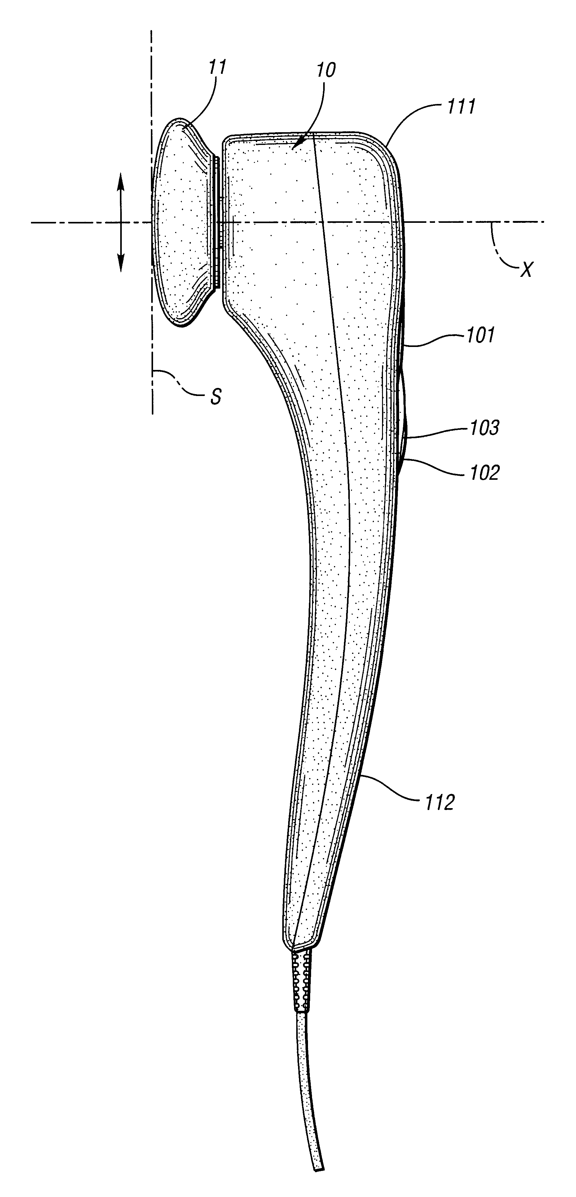
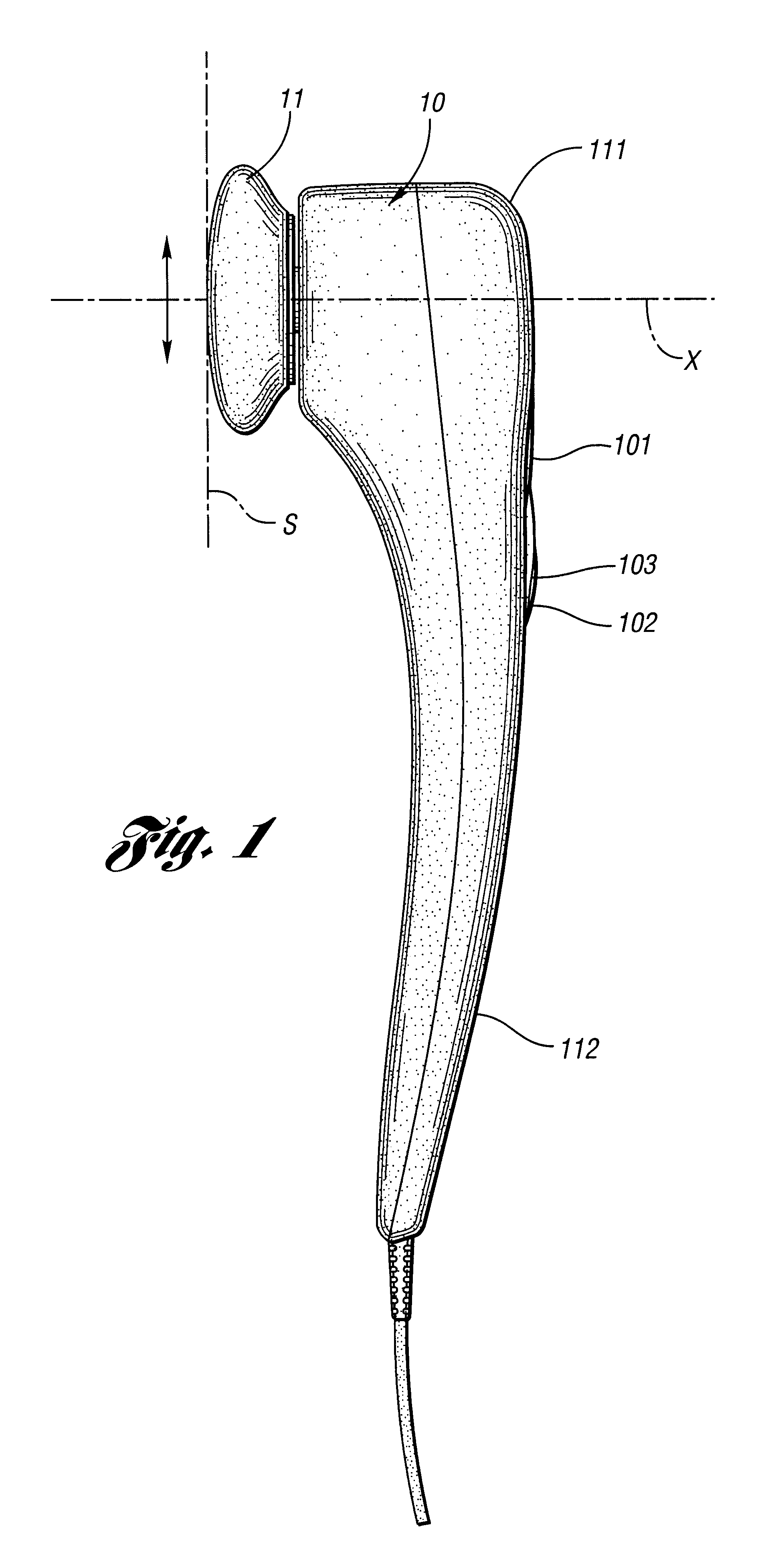
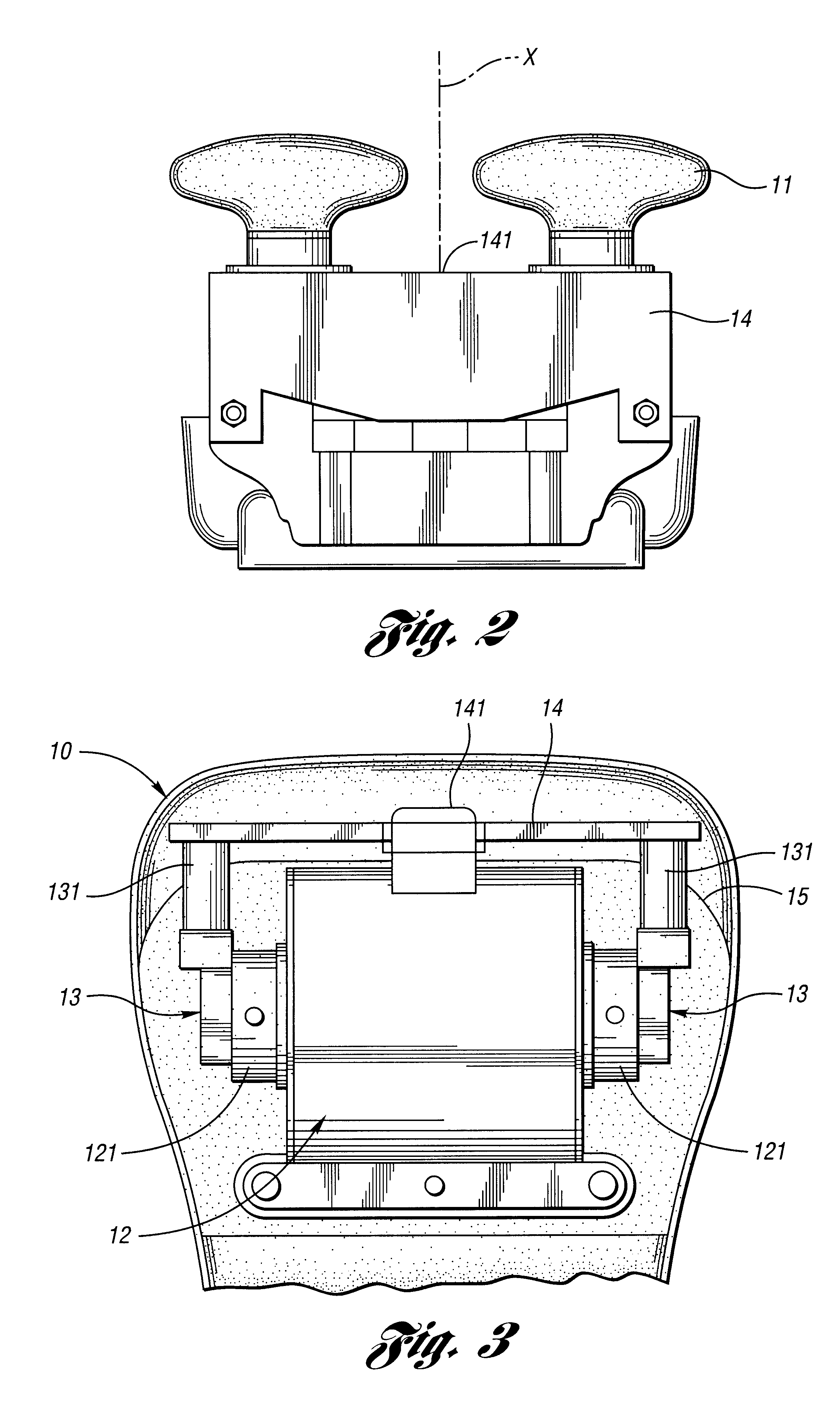
With reference to FIGS. 1, 2, 3 and 4, the massager in accordance with the present invention has a housing (10) having head portion (111), an elongated laterally extending handle (112), a pair of massage nodes (111), a bridge (14), a motor (12) and a pair of linkages (13).

The motor (12) is securely mounted in the head portion (111) of housing (10) with a motor bracket (not numbered) and has a motor shaft (121) extending from each end of the motor (12). Each of the linkages (13) is eccentrically and rotatably connected to an opposite end of the motor shaft (121). The eccentric connection points on the ends of the shaft (121) are diametrically opposite to each other. The bridge (14) is pivotally attached to the motor (12) retainer bracket by a pivotal connector (141) and is securely attached to both linkages (13) with corresponding flexible connecting arms (131).

With reference to FIGS. 5 and 6 and still taking FIG. 3 for reference, when the motor (12) runs, the rotation of the motor s...


PUM


Abstract

A massager has a motor with a motor shaft extending out from opposite ends of the motor, a pair of linkages each rotatably and eccentrically connected to opposite ends of the motor shaft, a bridge securely attached to the linkages with a pair of flexible arms and a pair of massage nodes securely mounted on the bridge. The bridge is pivotal relative to the housing so that the movement of the linkages caused by the rotation of the motor shaft drives the massage nodes on opposite sides of the bridge to pivotally reciprocate laterally, providing a rubbing massage effect.

Description

1. Field of the InventionThe present invention relates to a massager, and more particularly to a massager with a bridge pivotally mounted on the massager and a pair of massage nodes detachably connected to opposite ends of the bridge so as to create a rubbing and massage effect to the user when the bridge is in operation.2. Description of Related ArtWith reference to FIGS. 7 and 8, a conventional massager (50) comprises a motor (51), a pair of linkages (52) and a pair of massage balls (53). The linkages (52) are eccentrically connected to opposite ends of the motor shaft (not shown). Each of the massage balls (53) is securely engaged with one of the linkages (52). Because the linkages (52) are eccentrically engaged with the motor shaft, the motor (51) will thus drive and move the linkages (52). That is, the rotational movement of the motor shaft will be transformed into reciprocating movement of the linkage (52). Accordingly, the balls (53) securely mounted on the linkages (52) will...

Claims


Application Information

Patent Timeline
Patent Type & Authority Patents(United States)
IPC IPC(8): A61H23/02
CPCA61H23/0254A61H2201/0153A61H2201/1678A61H2203/0456A61H2205/10
Inventor HUANG, CHIEN-MING
Owner FKA DISTRIBUTING CO LLC
Why Eureka
Try Eureka