
Backup power supply for restraint control module

a technology for restraint control and power supply system, which is applied in emergency power supply arrangements, pedestrian/occupant safety arrangements, vehicular safety arrangements, etc., and can solve problems such as power loss, inability to function properly, and power loss of electronic components of airbag systems

Inactive Publication Date: 2004-05-04
AUTOLIV ASP INC +1
View PDF11 Cites 76 Cited by
  • Summary
  • Abstract
  • Description
  • Claims
  • Application Information

AI Technical Summary

Benefits of technology

The present invention is about a backup power supply system for a restraint control module. The system includes a main power source, a backup power source, a boost converter control and driver circuit, a backup power source charging circuit, and a backup power supply control and driver circuit. The main power source provides power to the restraint control module during normal operation. The boost converter control and driver circuit charges the backup power source when the main power source fails. The backup power supply control and driver circuit switches the source of power to the restraint control module if a loss of power is sensed. The system also includes an over-current protection circuit to prevent damage to the boost converter control and driver circuit. The technical effect of this invention is to ensure a reliable power supply for the restraint control module even in the event of a power loss or other malfunctions.

Problems solved by technology

During some automotive accidents, the electrical conductors that connect the battery to the air bag system and its related electronic components may become severed or damages so that power is cut off to these systems.
As a result of the conductor being severed or damaged, the electronic components of the air bag system lose power and will not function properly due to the loss of power.

Method used


Image

  • Backup power supply for restraint control module
  • Backup power supply for restraint control module
  • Backup power supply for restraint control module

Examples


Embodiment Construction

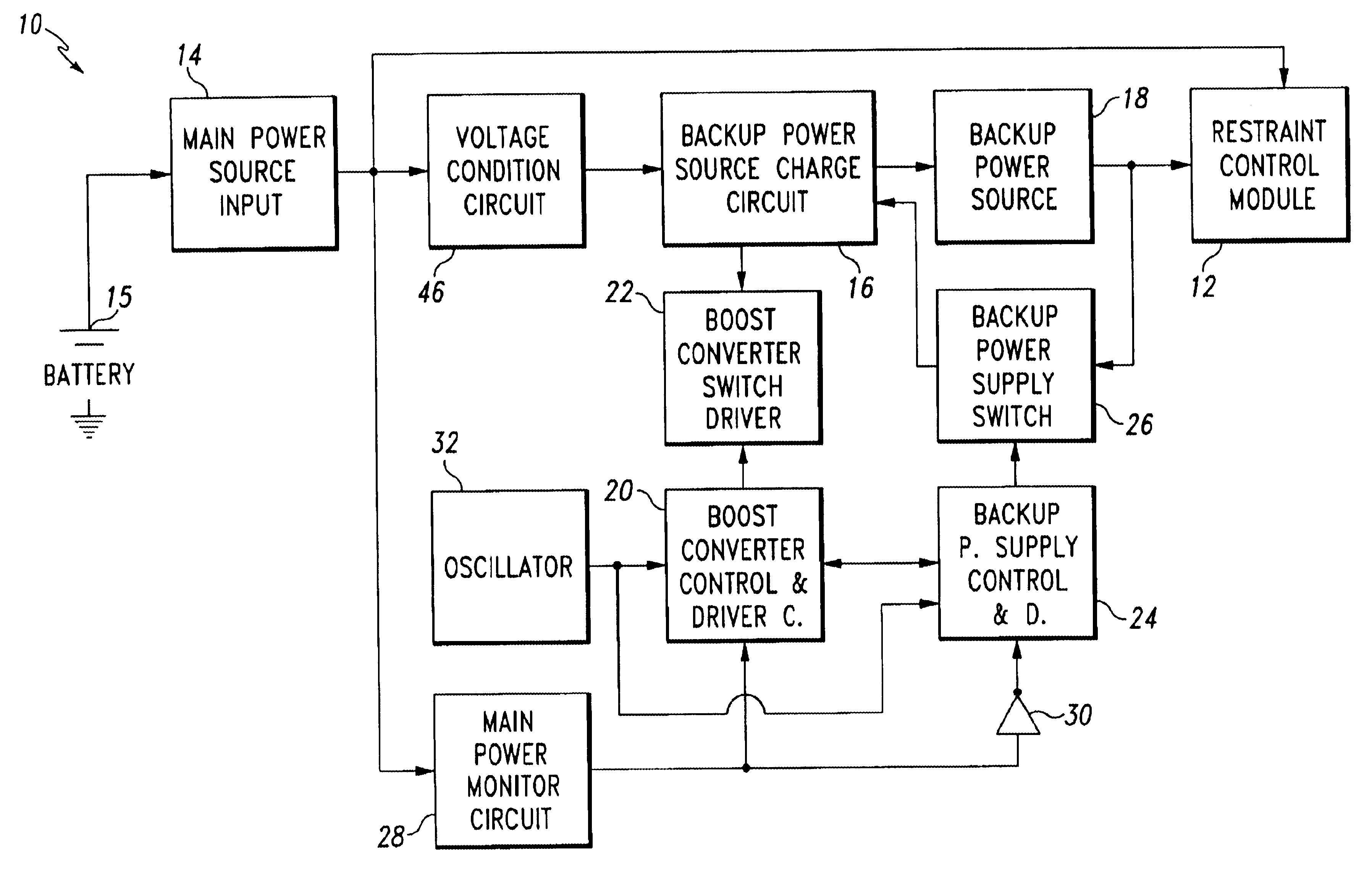
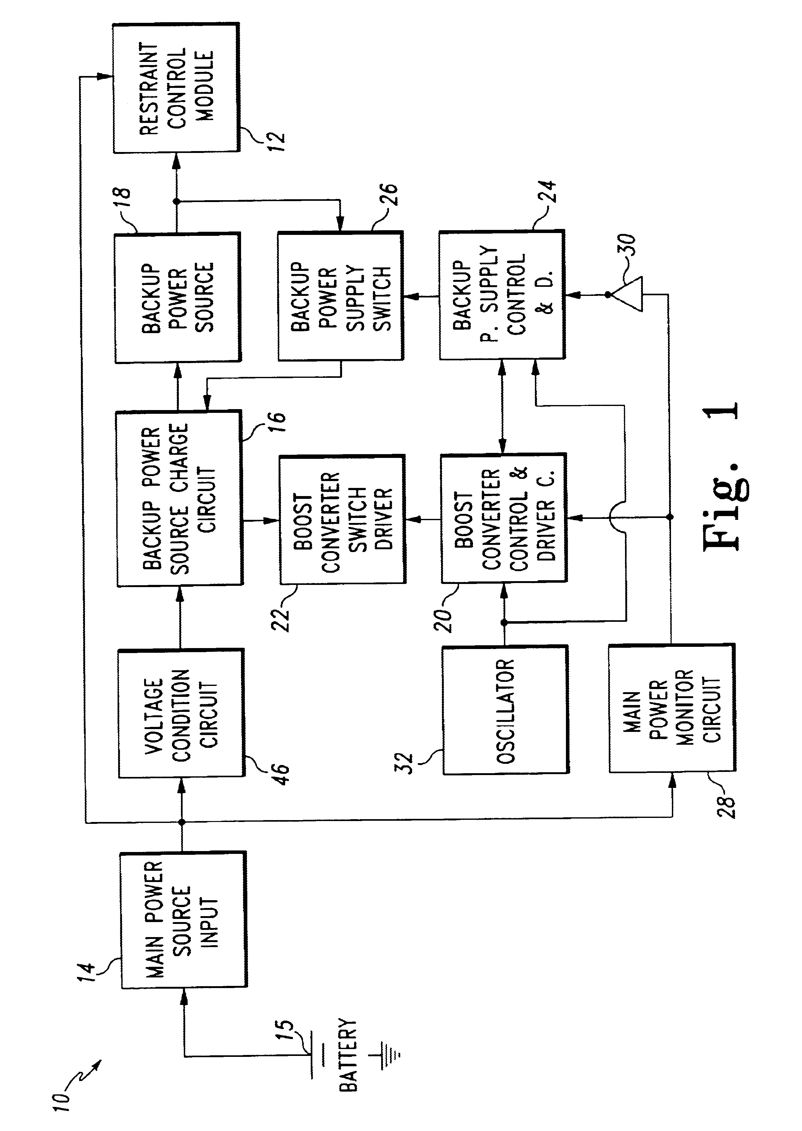
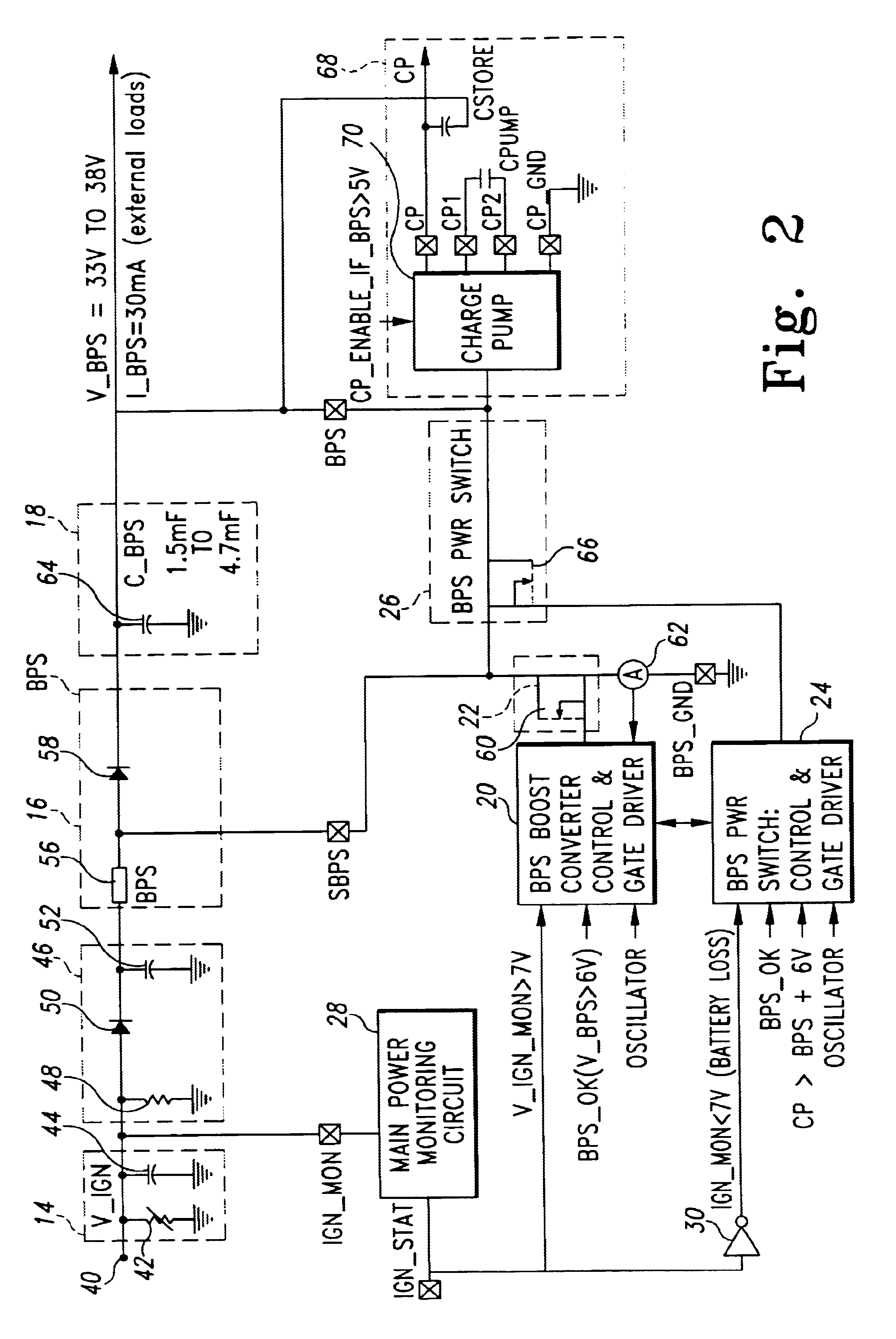
Referring to FIG. 1, a preferred embodiment of a backup power supply system 10 for a restraint control module 12 is illustrated. The backup power supply system 10 includes a main power source 14 that is connected to a backup power source charging circuit 16 and the restraint control module 12. During normal operation, the backup power source charging circuit 16 is used to initially charge and maintain a predetermined level of charge on a backup power source 18 that is connected to the output of the backup power source charging circuit 16. The output of the backup power source 18 is connected to the restraint control module 12 so that the backup power source 18 can provide power to the restraint control module 12 in the event of a loss of power from the main power source 14. The main power source 14 is also connected to the restraint control module 12 and provides power to the restraint control module 12 unless disconnected or taken out during an event experienced by the vehicle.

The ...


PUM


Abstract

A backup power supply for a restraint control module is disclosed that includes a main power source that is connected to a backup power source charging circuit. A boost converter control and driver circuit is connected with the main power source and the backup power source such that the boost converter control and driver circuit controls the charging of the backup power source with the main power source during normal operation. A backup power supply control and driver circuit is connected with a backup power supply switching device. The backup power supply control and driver circuit switches the source of power from the main power source to the backup power source when the backup power supply control circuit senses a loss of power from the main power source.

Description

The present invention relates generally to air bag systems for use as safety devices in automotive vehicles and, more particularly, to a backup power supply system for a restraint control module.Over the past several years, there has been a trend in the automotive industry to install air bag systems in vehicles to enhance protection traditionally afforded vehicle occupants through the use of seat belts. In some automotive vehicles, the inflatable restraint system may be an air bag system disposed within an occupant compartment in the automotive vehicle in close proximity to either a driver occupant or one or more passenger occupants. Usually, the air bag system includes a restraint control module that is connected to the vehicle structure and an air bag for deployment through an opening in a cover to extend and inflate in an occupant compartment of the automotive vehicle. The deployed air bag restrains movement of the occupant to protect the occupant from forcefully hitting parts of...

Claims


Application Information

Patent Timeline
Patent Type & Authority Patents(United States)
IPC IPC(8): H02J9/06
CPCH02J9/061
Inventor ROTHLEITNER, HUBERTBREUNIG, MICHAELBORAN, COLM PETERTIPPY, DAVID JAMESSENYK, MYRON IHORCOLAROSSI, VINCENT
Owner AUTOLIV ASP INC
Learn More