Vacuum system for milling machine

Inactive Publication Date: 2004-05-11
ROADTEC
View PDF31 Cites 63 Cited by
  • Summary
  • Abstract
  • Description
  • Claims
  • Application Information

AI Technical Summary

Benefits of technology

Among the advantages of the invention is that it obviates the requirement to employ a separate sweeper or vacuum truck in the milling process. Another advantage of the invention is that it provides a system for collec

Problems solved by technology

Without prior surface treatment, however, this method of repair generally results in the application of insufficient quantities of paving material in the rutted, potholed or otherwise damaged areas, because the overlayment will be applied at the same rate per unit of roadway width in damaged areas (which have a greater depth across the width) as in the undamaged areas.
The resulting reduced density in the overlayment of the previously damaged areas will lead to renewed rutting or other wear damage in the new pavement in relatively short order.
This can require the raisi

Method used


Image

  • Vacuum system for milling machine
  • Vacuum system for milling machine
  • Vacuum system for milling machine

Examples


Embodiment Construction

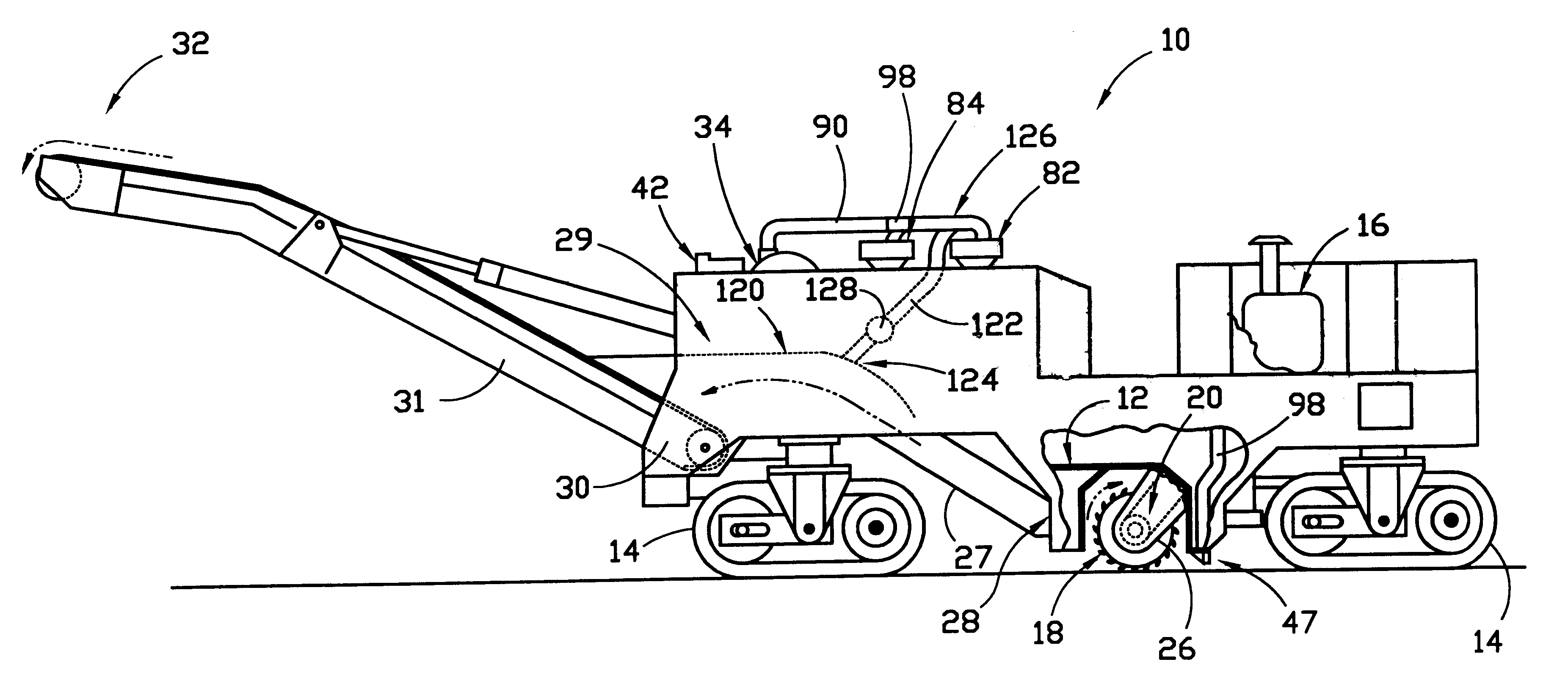
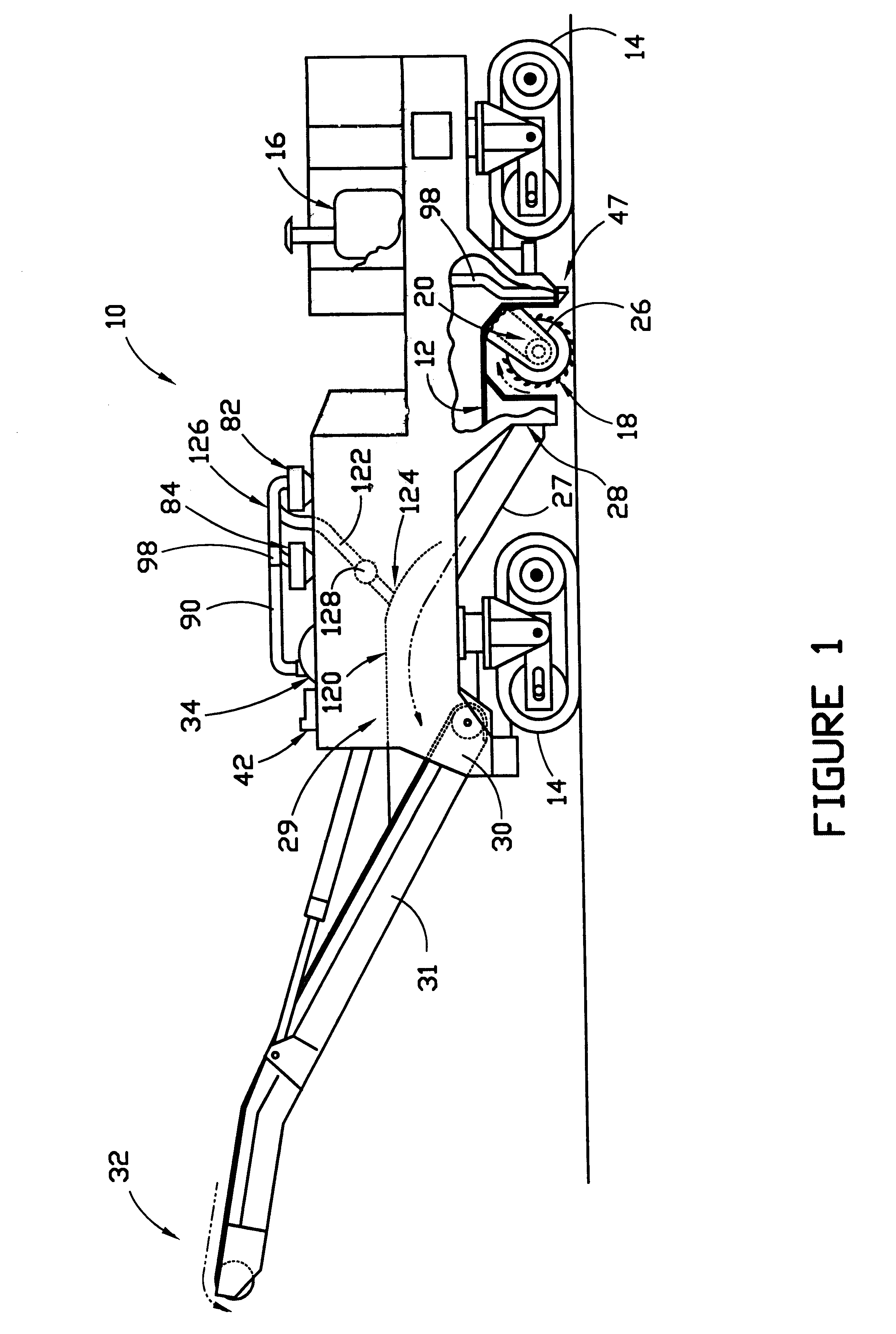
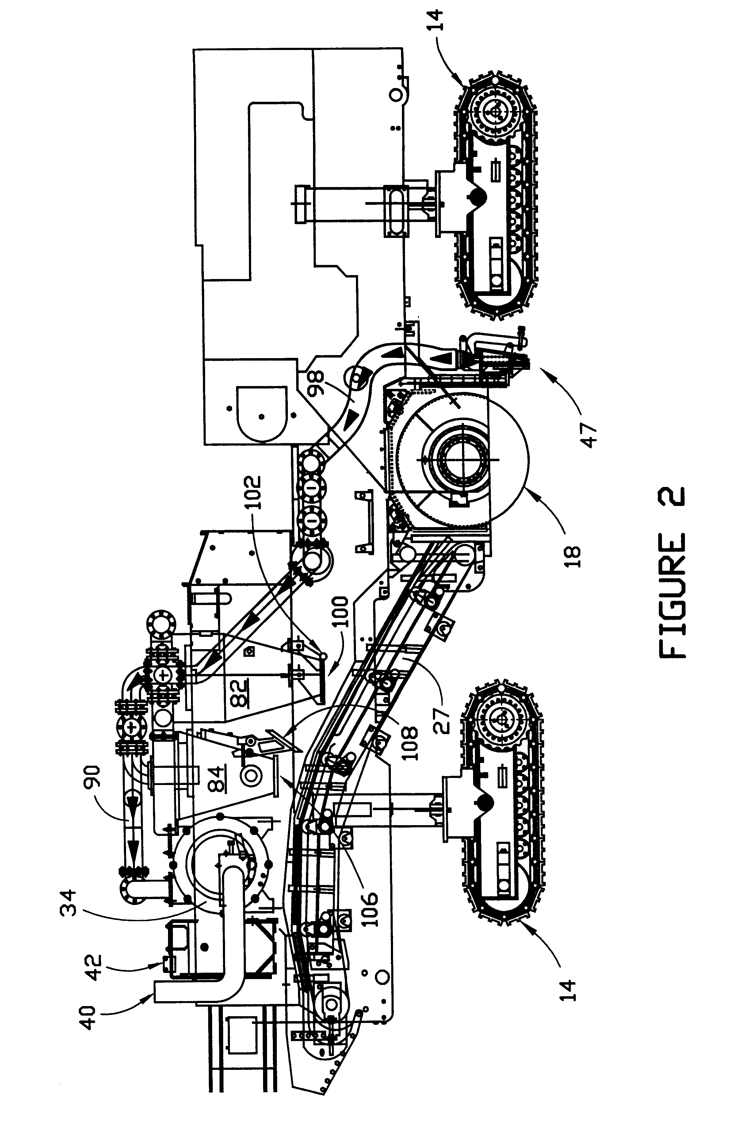
Referring now to the drawings, a milling machine embodying the features of a preferred embodiment of the present invention is indicated generally at 10. This machine comprises a portable or mobile vehicle having a frame, a portion of which is shown at 12, and three ground-engaging tracks 14 (two of which are shown in FIG. 1). The invention may also be employed in connection with a track-driven machine having two or four ground-engaging tracks or in connection with a wheel-driven machine. As is conventional, the tracks of the illustrated machine may all be steerable to provide precise directional control, and they are typically driven by hydraulic motors (not shown), which in turn are powered by a propulsion system such as engine 16, to advance the machine across the surface of a roadway, parking lot or other surface to be milled. The machine includes a milling drum 18 which is adapted for cutting a width of material from the surface in the path of the machine. The milling drum is mo...


PUM


Abstract

A vacuum system is mounted on a portable milling machine for extracting material cut by the milling drum of the machine from the surface of a roadway. The milling machine includes a frame, a propulsion system for advancing the machine across a surface to be milled, a milling drum mounted on the frame for rotation about its axis, and a conveyor for conveying material cut by the milling drum away from the drum. The vacuum system includes a vacuum pump having an air inlet and an air outlet and a nozzle mounted behind the milling drum having an opening for receiving material cut from the surface by the drum. The vacuum system also includes a material collector having an inlet, an air outlet and a material outlet. The collector is adapted for collecting material entrained in air by the pump through the collector inlet and for discharging such material through the material outlet onto the conveyor. The vacuum system also includes a first conduit and a second conduit. The first conduit connects the nozzle and the inlet of the material collector, and the second conduit connects the air, outlet of the material collector and the air inlet of the pump.

Description

This invention relates generally to milling or cold-planing machines for milling concrete or asphalt pavements. More specifically, the invention relates to a vacuum system for removing the millings or cuttings cut by the milling machine from the roadway.BACKGROUND AND DESCRIPTION OF THE PRIOR ARTRoadway repair is often accomplished by overlaying the existing pavement (whether of concrete or asphalt composition) with a new layer (often called a leveling course) of concrete, asphalt or other surfacing materials. Without prior surface treatment, however, this method of repair generally results in the application of insufficient quantities of paving material in the rutted, potholed or otherwise damaged areas, because the overlayment will be applied at the same rate per unit of roadway width in damaged areas (which have a greater depth across the width) as in the undamaged areas. The resulting reduced density in the overlayment of the previously damaged areas will lead to renewed rutting...

Claims


Application Information

Patent Timeline
IPC IPC(8): E01C23/088E01C23/00
CPCE01C23/088E01C2301/50
Inventor MCSHARRY, CHRISCAMPBELL, THOMAS R.
Owner ROADTEC
Why Eureka
Try Eureka