
Device for the vertical and automatic wedging of a vehicle seat

a vehicle seat and vertical wedging technology, applied in the direction of seat furniture, machine supports, domestic objects, etc., can solve the problems of generating noise and discomfort for the occupants

Inactive Publication Date: 2004-05-18
GRUPO ANTOLIN ING
View PDF16 Cites 37 Cited by
  • Summary
  • Abstract
  • Description
  • Claims
  • Application Information

AI Technical Summary

Benefits of technology

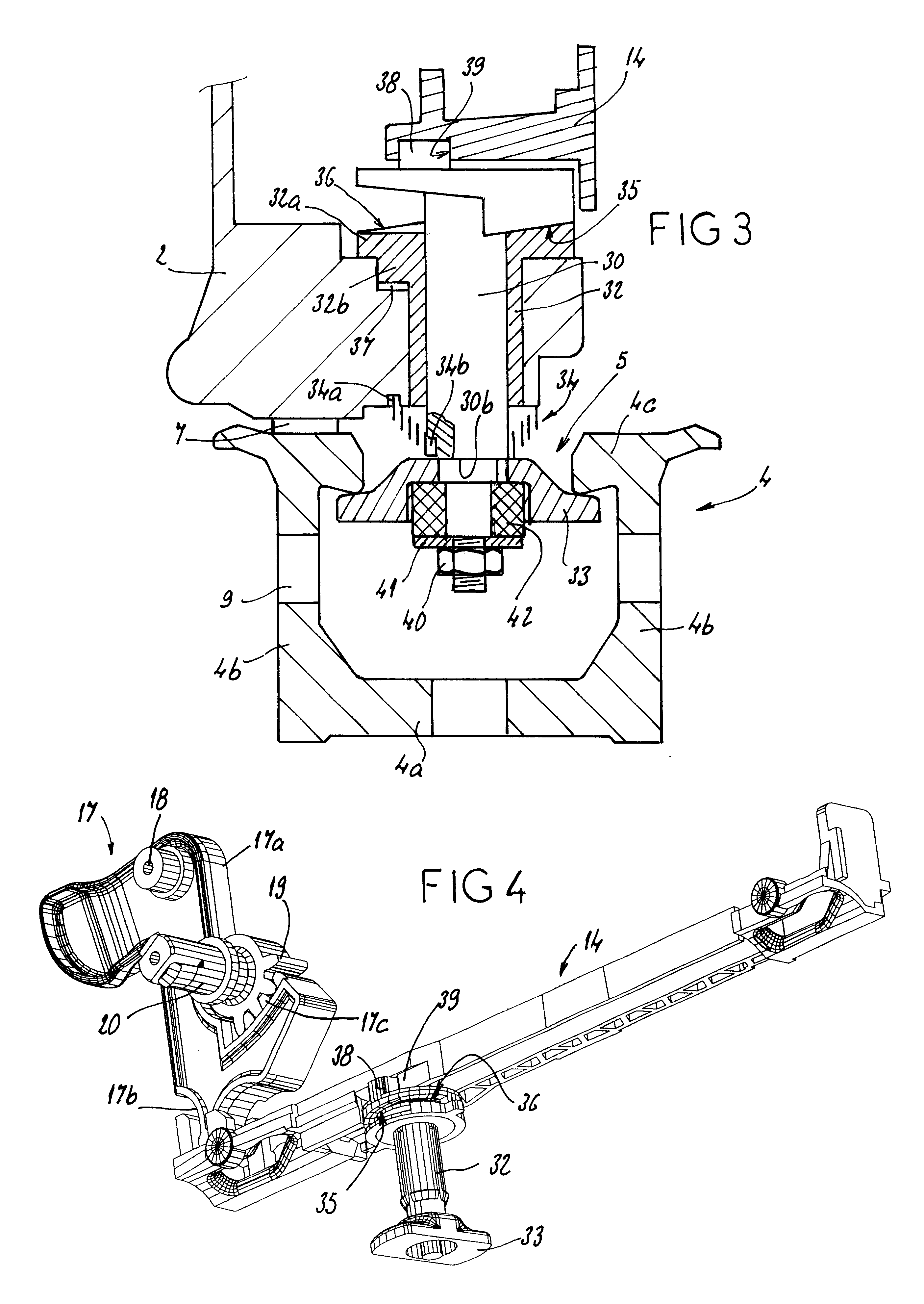
Thus, each, right or left, subassembly of the seat is equipped with a wedging member which is normally in a wedging position but which, when the runners with which this seat is equipped are introduced into the slideways, is brought into a position of introduction into these slideways. As soon as the seat is positioned therein and the operator stops actuating the journal control means, the return spring associated with each of them returns them to their rest position, in which position the wedging member is arranged transversely to the groove of each slideway. During this rotation, the helical ramp of each journal comes to bear against a complementary bearing surface and causes the journal to move vertically, this having the effect of bringing the wedging member into contact with the underside of the returns of the slideway in which it is arranged, thus ensuring positive connection between the seat and its slideways.
The result of this is that, whatever the functional clearances resulting from the spread of manufacturing tolerances, the underframe is connected to the slideways to eliminate the generation of any noise and any vertical movements, and also horizontal ones, because of the clearance between the catches and the housings accommodating them.

Problems solved by technology

In spite of the care taken in manufacturing the components of the underframe, in assembling these components and in fitting the slideways, the build-up of manufacturing tolerances may, in certain seat / slideway combinations, form vertical clearances which, even when the seat is wedged and locked in its slideways, encourage vertical movements of small amplitude but which generate noise and discomfort to the occupant.

Method used


Image

  • Device for the vertical and automatic wedging of a vehicle seat
  • Device for the vertical and automatic wedging of a vehicle seat
  • Device for the vertical and automatic wedging of a vehicle seat

Examples


Embodiment Construction

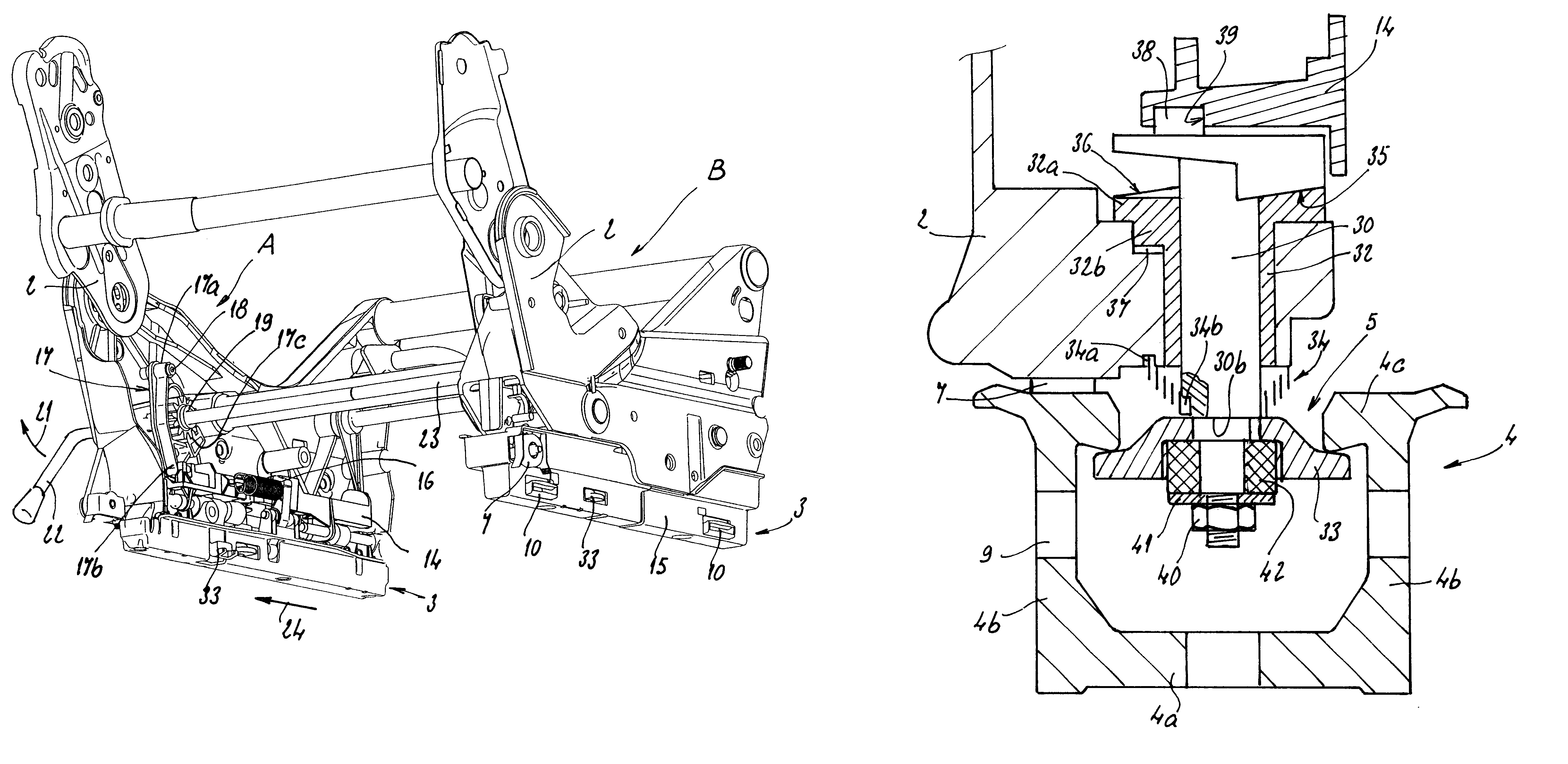
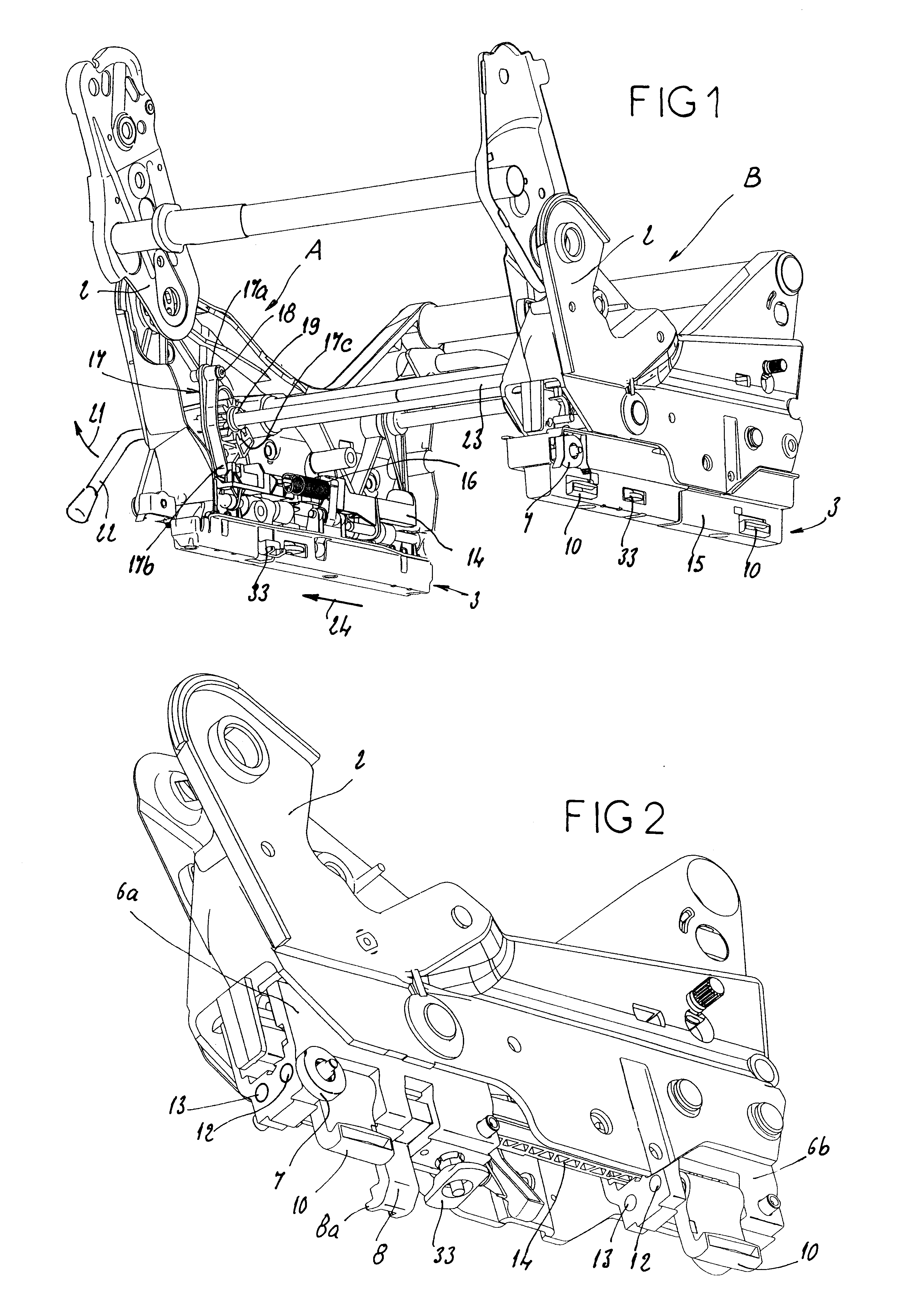
As shown in FIG. 1, the device according to the invention applies to a seat the seat-part structure of which is made up of two subassemblies, namely a left-hand one A and a right-hand one B, forming an underframe. Each of these subassemblies comprises a rigid sideplate 2, made of cast metal alloy, and the lower part of which is in the shape of a runner 3 able to run in a slideway 4. As shown in FIGS. 3 and 5, the slideway 4 is in the shape of a C, that is to say made up of a web 4a bordered by two flanges 4b equipped, at their upper free end, with an internal return 4c delimiting, with the return opposite, a groove 5.

Each subassembly of the underframe comprises an internal structure bearing directly, or via carriages 6a, 6b as shown in FIG. 2:

rollers 7, able to roll along the returns 4c of the slideway,

catches 8, the teeth 8a of which are able to collaborate with apertures 9 made in the flanges 4b of the slideway,

and hooks 10 able to sit under the internal returns 4c of the slideway...


PUM


Abstract

A device for wedging an adjustable removable seat vertically in a C-shaped slideway, the seat being secured to an underframe having a subassembly able to run in the C-shaped slideway, the subassembly including a catch collaborating with a return of the slideway, and a retaining hook able to collaborate with the return of the slideway when the seat is subjected to an impact energy, the device including a vertical journal mounted to rotate in a bearing of the underframe, a member for wedging in terms of vertical translation, connected in terms of rotation to a lower end of the journal and having, when viewed from above, a generally rectangular overall shape a shortest dimension of the rectangular shape being less than a width of a groove of the C-shaped slideway and a longest dimension of the rectangular shape being greater than the width of the groove, so as to be able, in a wedged position, to sit under the internal returns of the slideway, a spring constantly returning the wedging member to the wedged position, a pivoting means for pivoting the journal against action of a return spring of the journal into a position in which the wedging member can be engaged in the groove of the slideway, and a helical ramp, rotatable with the journal to collaborate with a fixed complementary bearing surface to move the wedging member vertically into contact with the return of the slideway.

Description

The invention relates to a device for the vertical and automatic wedging in C-shaped slideways of a vehicle removable seat. It relates more especially to removable seats comprising, on the one hand, means of positioning in longitudinal slideways fixed to the floor of the vehicle and, on the other hand, retaining hooks able to collaborate with the internal returns of the slideway when the seat is subjected to impact energy and, in addition, means allowing their longitudinal position to be adjusted, with locking in the chosen position.DESCRIPTION OF THE PRIOR ARTIn these seats, the seat-part structure is secured to an underframe formed of two subassemblies, namely a right-hand one and a left-hand one, each comprising a rigid sideplate the lower part of which is set out in the form of a runner to run in a C-shaped slideway, and, borne by this runner:catches, collaborating with returns, teeth or notches of the slideway,retaining hooks,and an actuator connected to control means borne by ...

Claims


Application Information

Patent Timeline
IPC IPC(8): B60N2/42B60N2/005B60N2/015
CPCB60N2/01541B60N2/01566B60N2/42
Inventor CHABANNE, JEAN-PIERRECHATEAU, JEAN
Owner GRUPO ANTOLIN ING
Learn More