Pump impeller, method of producing pump impeller, and pump with the pump impeller

a technology of pump impeller and impeller, which is applied in the field of pump impeller, method of producing pump impeller, and pump impeller with pump, can solve the problem of not being able to loosen the bearing, and achieve the effect of optimal venting

Active Publication Date: 2021-02-02
BUHLER MOTOR GMBH
View PDF9 Cites 0 Cited by
  • Summary
  • Abstract
  • Description
  • Claims
  • Application Information

AI Technical Summary

Benefits of technology

[0004]The object of the invention is therefore to provide a robust construction, optimal venting, secure attachment of the bearing component, economic production, and a possibility of axial length tolerance compensation, given a pump impeller with a plastic-bonded permanent magnet. Furthermore, an optimally accurate unbalance-reduced connection between the bearing component and the magnet material should be producible.
[0010]The geometry of the bearing component and of the hollow shaft is designed in such a way that they are arranged radially positively relatively to one another. This allows for pre-centering and facilitates attaching of the bearing component to the hollow shaft, safe handling, and reliable insertion into an injection molding tool, in particular when an assembly robot is used. When using a cone shape, the plug-in connection is even more optimal.
[0015]A plurality of axial openings are provided in the connecting region. These openings on the one hand serve for venting during the injection molding process and on the other hand as vibration decoupling means during operation of the pump, since the openings reduce the radial stiffness of the bearing component.
[0019]The outer region of the bearing component is provided with a radially projecting rib. This rib brings about a positive connection to the magnet material. The rib may be arranged centrally, eccentrically, or at the ends of the outer region. A plurality of ribs or differently shaped projections can also be used. The same applies to the use of a groove or of recesses in the outer region of the bearing component. If ribs or grooves are used, they can have a discontinuity. A positive fit in the direction of rotation is hereby also given so that a rotation of the parts relative to one another is prevented. A positive connection having the same effect can also be produced by a crenellated formation of edges of the outer region. A single projection or recess is also sufficient. However, an approximately centrally arranged rib can be produced most simply because these ribs can also be formed as enlarged mold release flashing. The bearing component (4) is designed as a radial bearing in the described example. However, it is conceivable to also apply the same method for axial bearings.
[0022]The injection molding tool contains magnets which cause a pre-magnetization or full magnetization of the permanent magnet material. This influences the flow path of the magnet material in such a way that it initially moves along the periphery of the cavity and changes direction at the end of the latter. In the case of conventional methods, air inclusions routinely occur in the process. In this case, however, the air can escape via the gap between the hollow shaft and the bearing component. Surprisingly, it has been found that the position of the gap in a central region brings about optimal venting.

Problems solved by technology

It is therefore not possible for the bearing to work loose.

Method used


Image

  • Pump impeller, method of producing pump impeller, and pump with the pump impeller
  • Pump impeller, method of producing pump impeller, and pump with the pump impeller

Examples


Embodiment Construction

[0027]In describing preferred embodiments of the present invention illustrated in the drawings, specific terminology is employed for the sake of clarity. However, the invention is not intended to be limited to the specific terminology so selected, and it is to be understood that each specific element includes all technical equivalents that operate in a similar manner to accomplish a similar purpose.

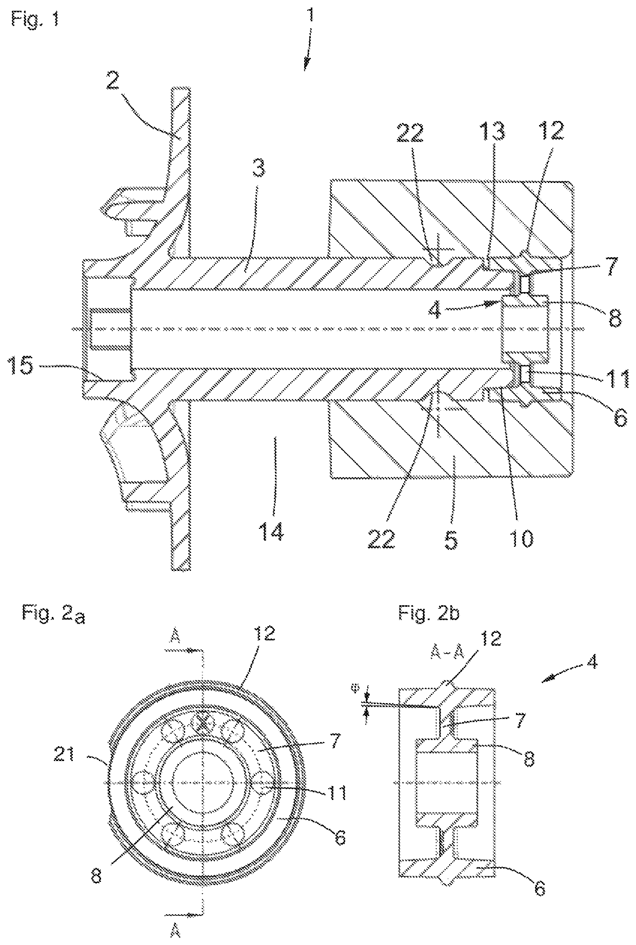
[0028]FIG. 1 shows a sectional view of a pump impeller 1 having: an impeller wheel 2 which is integral with a hollow shaft 3; a bearing component 4; and a permanent magnet 5. Arranged axially between the hollow shaft 3 and the bearing component 4 is a gap 13 which is of groove-like design and whose groove bottom is formed by the hollow shaft 3. The lateral surfaces of the groove are formed on the one hand by the hollow shaft 3 and on the other hand by the bearing component 4. The gap 13 is filled with magnet material of the permanent magnet 5. There is a free space 14 between the permanen...


PUM

PropertyMeasurementUnit
half cone angleaaaaaaaaaa
thicknessaaaaaaaaaa
angleaaaaaaaaaa

Abstract

A pump impeller consisting of at least three different material regions, wherein an impeller wheel with a hollow shaft defines a first material region, a bearing component defines a second material region, and a permanent magnet defines a third material region. The invention furthermore relates to a method for producing the pump impeller, and to a centrifugal pump with the pump impeller. The object of the invention is to provide a robust construction, optimal venting, secure attachment of the bearing component, economic production, and a possibility of axial length tolerance compensation given a pump impeller with plastic-bonded permanent magnets. Furthermore, an optimally accurate unbalance-reduced connection between the bearing component and the magnet material should be producible.

Description

CROSS-REFERENCE TO RELATED APPLICATIONS[0001]The present patent application is based on, and claims priority from, German Application No. DE 10 2018 201 841.3, filed on Feb. 6, 2018, which is incorporated herein by reference in its entirety.BACKGROUND OF THE INVENTION(1) Field of the Invention[0002]The invention relates to a pump impeller consisting of an impeller wheel with a hollow shaft, a bearing component, and a permanent magnet. The invention furthermore relates to a method for producing the pump impeller and to a centrifugal pump with the pump impeller.(2) Description of Related Art Including Information Disclosed Under 37 CFR 1.97 and 1.98[0003]Pump impellers for auxiliary water pumps in motor vehicles or similar applications are frequently provided with plastic-bonded permanent magnets. Both single-piece and multi-part pump impellers are known. In single-piece pump impellers, both the motor and the hydraulic part consist of permanent magnet material. For economic reasons, a...

Claims


Application Information

Patent Timeline
Patent Type & Authority Patents(United States)
IPC IPC(8): F04D29/048F04D29/62B29C45/00F04D13/06F04D29/02F04D13/02B29C45/14B29L31/00F04D1/00
CPCF04D29/048B29C45/0001B29C45/14467F04D13/024F04D13/06F04D29/026F04D29/628B29K2995/0008B29L2031/7496F04D1/00F05D2300/43F04D29/2227
Inventor KRIPPNER, SEBASTIANBINDIG, ANDREARAUSCH, HARALDEHRSAM, JÜRGENWEISKE, KLAUS
Owner BUHLER MOTOR GMBH
Why Eureka
Try Eureka