

Circuit topology for attenuator and switch circuits
a switch circuit and circuit topology technology, applied in the field of circuit topology for attenuator and switch circuit, can solve the problems of increased parasitic capacitance of the device, impedance mismatch,
- Summary
- Abstract
- Description
- Claims
- Application Information
AI Technical Summary
Benefits of technology
Problems solved by technology
Method used
Image

Examples
Embodiment Construction
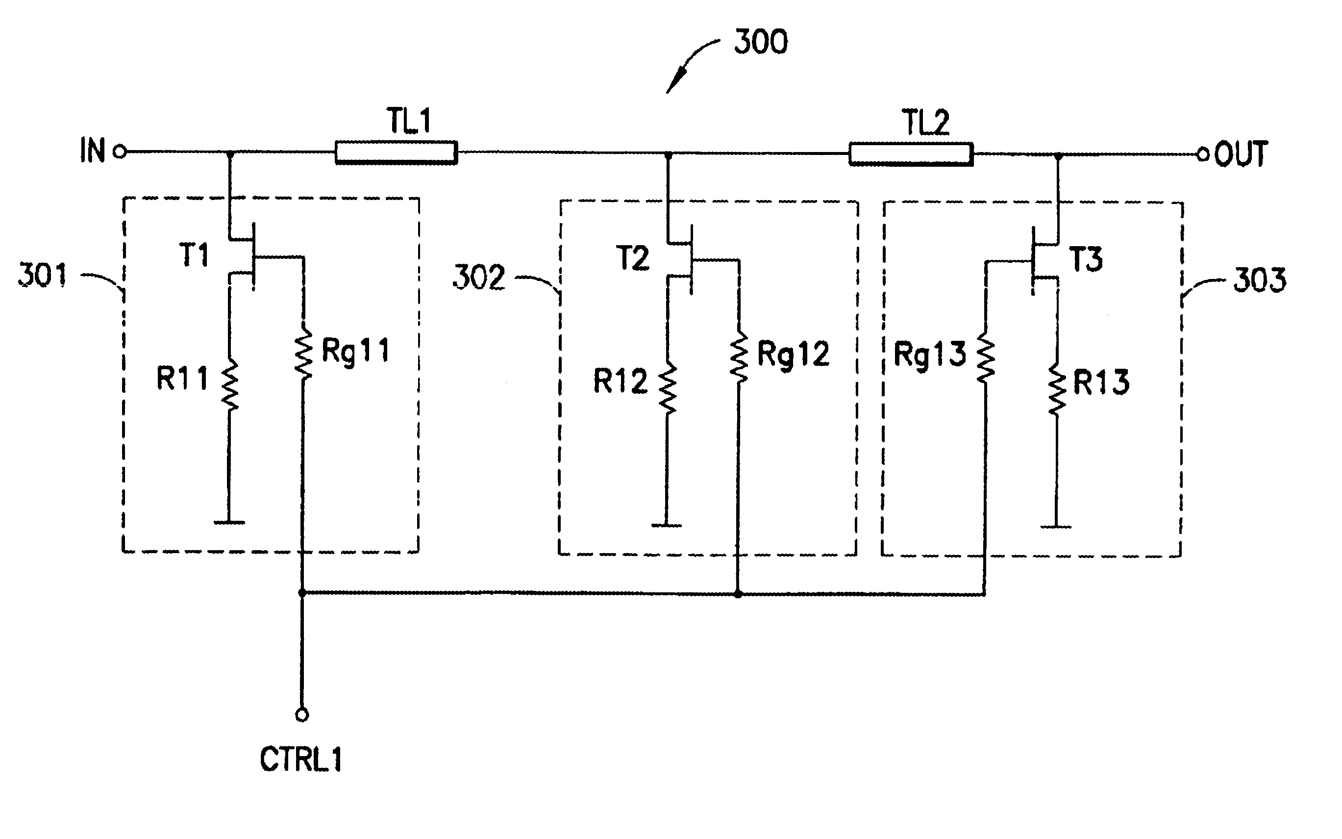
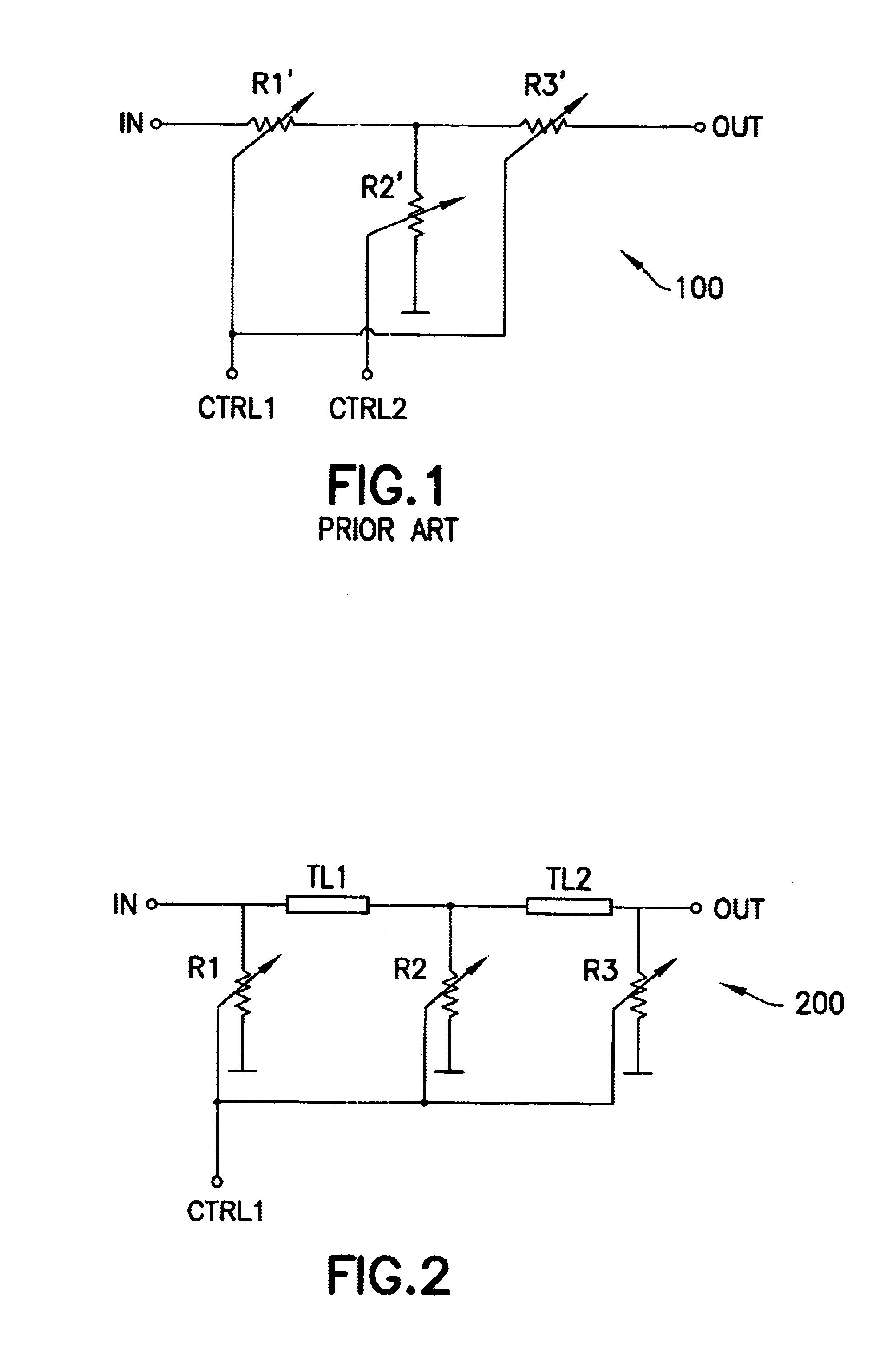
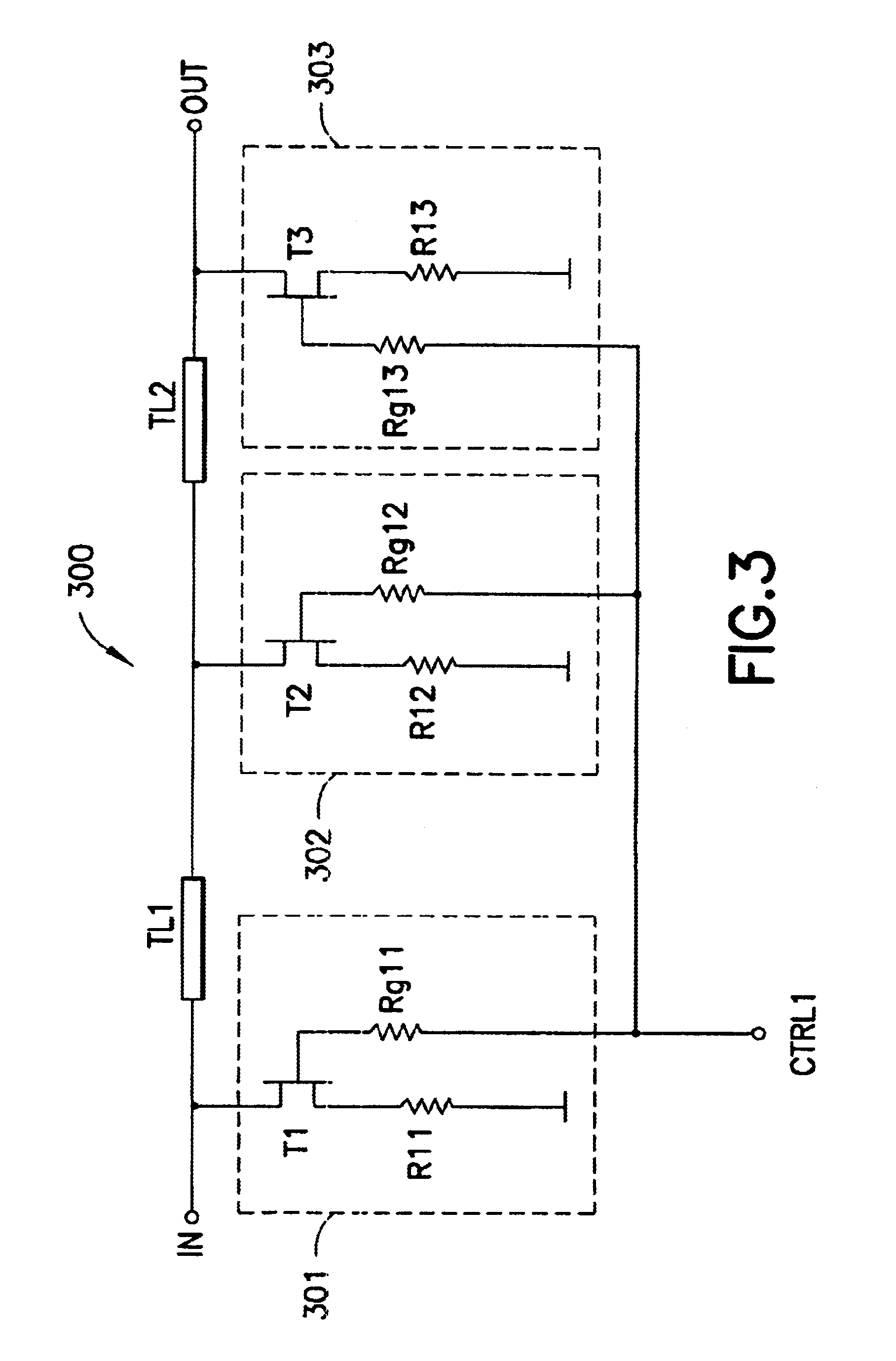
A low-loss attenuator circuit 200 according to the present invention is shown in FIG. 2. The circuit 200 includes first and second transmission lines TL1, TL2 connected in series between an input terminal IN and an output terminal OUT. The circuit 200 further includes three variable shunt elements R1, R2, R3 connected to ground. The first variable shunt element R1 is connected between the input terminal IN and the first transmission line TL1, the second variable shunt element R2 is connected between the first and second transmission lines TL1, TL2, and the third variable shunt element R3 is connected between the second transmission line TL2 and the output terminal OUT. The impedance of each of the three shunt elements R1, R2, R3 is controlled by a single control signal CTRL1.
To attain minimum attenuation, each of the three shunt elements R1, R2, R3 is at a high resistance. Attenuation of an input signal is achieved by adjusting the control signal CTRL1 to lower the resistance of the...
PUM
 Abstract
Description
Claims
Application Information