Optical transducers and methods of making same

a technology of optical transducers and optical transducers, which is applied in the field of optical transducers, can solve the problems of large influence on sensitivity and reliability, difficult to produce such optical transducers in volume and at relatively low cost, and require extremely high precision in the manufacture and assembly of their respective parts. to achieve the effect of maximizing the effective surface and low cos

Inactive Publication Date: 2004-05-25
PHONE OR
View PDF4 Cites 40 Cited by
  • Summary
  • Abstract
  • Description
  • Claims
  • Application Information

AI Technical Summary

Benefits of technology

One object of the present invention is to provide a method of producing optical transducers in a manner which permits mass production at relatively low cost. Another object of the invention is to provide a novel optical transducer of an efficient construction which maximizes the effective surfaces of the light source and light detector exposed in the optical window of the transducer.
As will be described more particularly below, such an optical transducer readily lends itself to mass-production. It also minimizes the shading effect of the light detector and maximizes the effective surface of the light source and light detector exposed in the optical window, thereby improving the sensitivity of the optical transducer to the displacements of the displaceable member.
As will be described more particularly below, the foregoing features not only permit the optical units of the transducers to be produced in volume and at low cost, but also provide an efficient construction maximizing the effective surfaces of the light source and light detector exposed to the displaceable member.

Problems solved by technology

As indicated earlier, such optical transducers, however, require extremely high precision in the manufacture and assembly of their respective parts, since very small dimensional errors can have a large affect on their sensitivity and reliability.
For these reasons, it is very difficult to produce such optical transducers in volume and at relatively low cost.

Method used


Image

  • Optical transducers and methods of making same
  • Optical transducers and methods of making same
  • Optical transducers and methods of making same

Examples


Embodiment Construction

. 2-5)

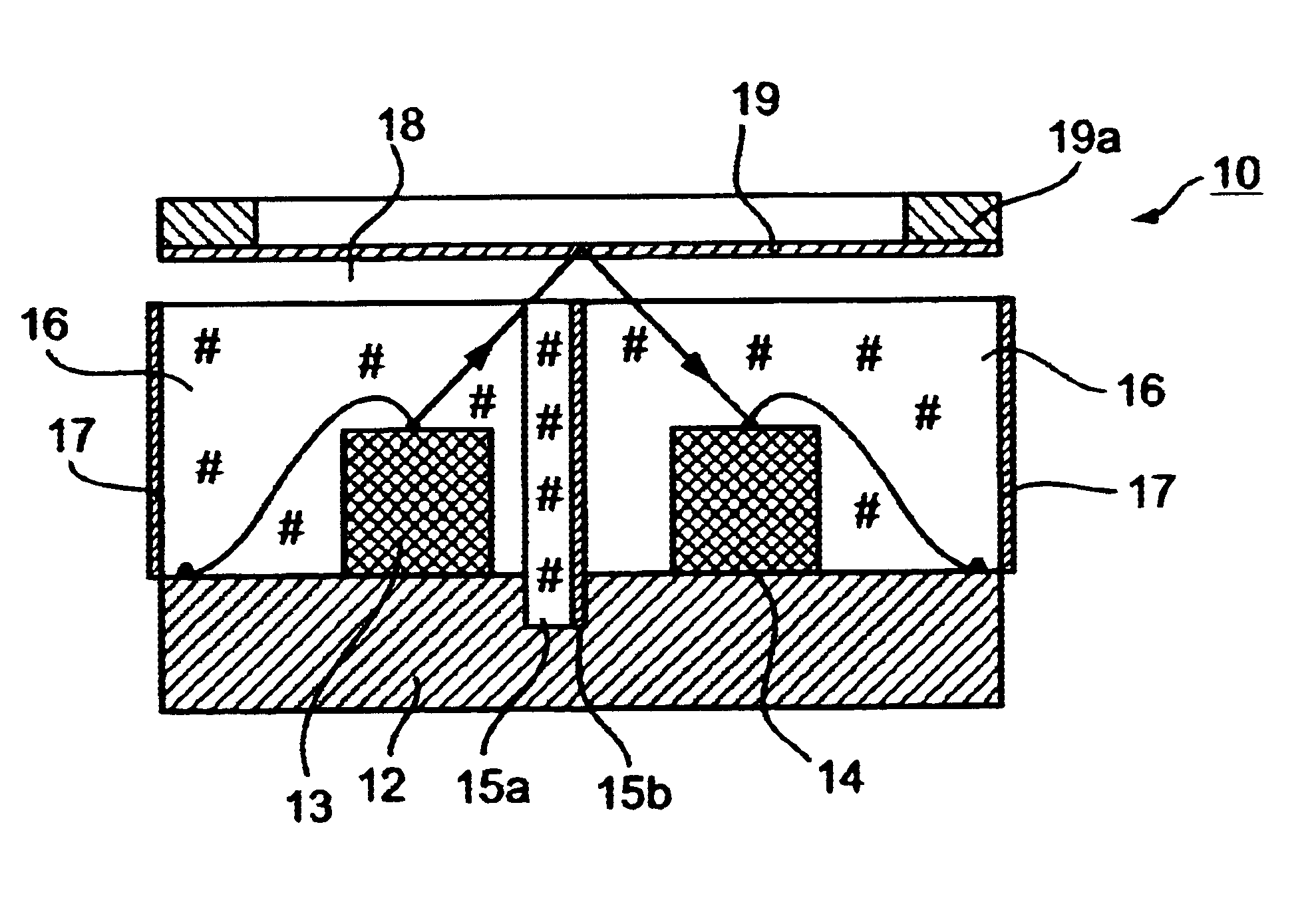
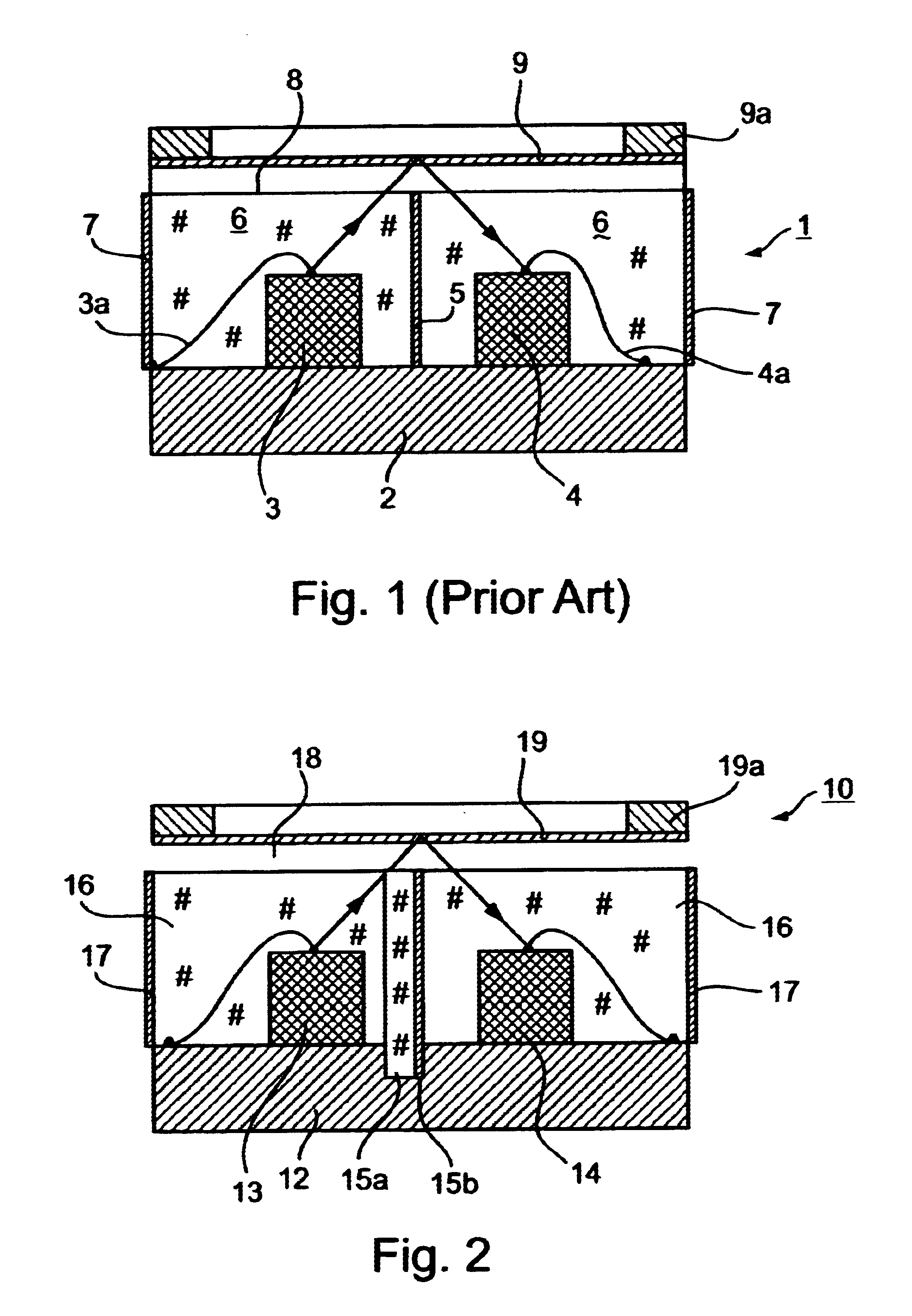
FIG. 2 schematically illustrates an optical transducer of the general type shown in FIG. 1 but modified in accordance with the present invention to provide the advantages of the present invention. An important modification is that, instead of forming the optical shield (6, FIG. 1) as a separate layer between the light source and the light detector, as in the prior art construction of FIG. 1, the light shield is in the form of a thin layer of a light-blocking material on a transparent plate, which transparent plate is fixed to the base member between the light source and light detector. As will be described more particularly below, these features, as well as other features of the present invention, permit highly-sensitive optical transducers to be produced in volume and at relatively low cost utilizing mass production techniques.

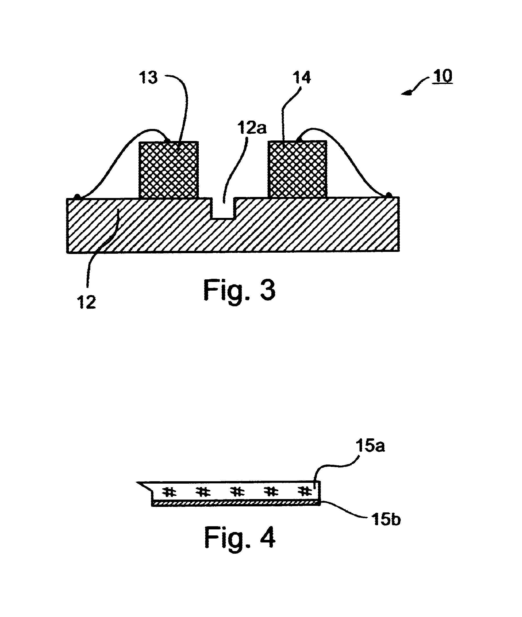
The optical transducer 10 illustrated in FIG. 2 is produced as follows:

First, the base member 12 (corresponding to base member 2 in FIG. 1) is formed w...


PUM


Abstract

An optical transducer includes a base member, a light source carried on a face of the base member, a light detector carried on the face of the base member laterally spaced from the light source, an optical shield extending from the face of the base member between the light source and light detector, and a displaceable member overlying, and spaced from, the light source, light detector and optical shield, and effective to reflect light from the light source to the light detector. The optical shield includes a transparent plate extending from the face of the base member between the light source and light detector, and carrying a thin layer of a light-blocking material to shield the light detector from direct exposure to the light source. The light source, light detector, and optical shield are all embedded in a transparent plastic potting material. Also described is a method of making such optical transducers by producing an intermediate matrix of a plurality of such light sources, light detectors and optical shields and cutting the matrix into individual optical units.

Description

FIELD AND BACKGROUND OF THE INVENTIONThe present invention relates to optical transducers (sometimes referred to as optical sensors) which utilize optical means for sensing mechanical displacements, such as movements of a body or deformation of a membrane, and converting them to electrical signals. The invention also relates to methods of making such optical transducers. The invention is particularly useful in making optical microphones, for converting sound into electrical signals, and is therefore described below especially with respect to this application.Optical transducers of this type are described, for example, in U.S. Pat. Nos. 5,771,091; 5,969,838; 6,091,497; and 6,239,865, the contents of which patents are incorporated herein by reference.Such optical transducers generally include an optical unit containing a light source, a laterally spaced light detector, an optical shield between the light source and light detector, and a displaceable member aligned with the optical win...

Claims


Application Information

Patent Timeline
Patent Type & Authority Patents(United States)
IPC IPC(8): H04R23/00
CPCH04R23/008H01L2224/48091H01L2924/00014
Inventor PARITSKY, ALEXANDERKOTS, ALEXANDER
Owner PHONE OR
Why Eureka
Try Eureka