Stator for reciprocating motor

a technology of reciprocating motors and stators, which is applied in the direction of dynamo-electric components, dynamo-electric machines, magnetic circuit shapes/forms/construction, etc., can solve the problems of complex laminating operation, unsuitable mass production, and low productivity, so as to improve assembly properties

Inactive Publication Date: 2004-05-25
LG ELECTRONICS INC
View PDF11 Cites 6 Cited by
  • Summary
  • Abstract
  • Description
  • Claims
  • Application Information

AI Technical Summary

Benefits of technology

Therefore, an object of the present invention is to provide a stator for a reciprocating motor of which components can be fabricated in simple way and assembling property can be improved.

Problems solved by technology

Thus, the laminating operation is complex, and productivity is lowered and it is not suitable for mass production.

Method used


Image

  • Stator for reciprocating motor
  • Stator for reciprocating motor
  • Stator for reciprocating motor

Examples


Embodiment Construction

The present invention will now be described with reference to accompanying drawings.

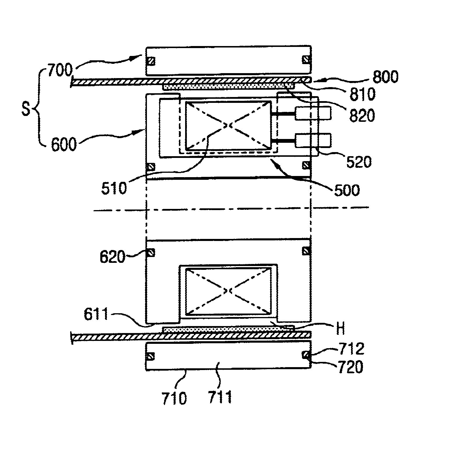
FIG. 5 shows a reciprocating motor including an embodiment of a stator according to the present invention. As shown therein, in the reciprocating motor, a terminal portion 520 for electrically connecting a coil 510 to outer electric source is formed integrally on an insulating bobbin 500 on which a coil 510 is wound.

In addition, a first lamination core 600 is coupled to outer side of the bobbin 500, and the first lamination core 600 is a laminated body in which a plurality of lamination sheets 610 formed as thin plates of U-shape are laminated in radial direction along with the bobbin 500.

The plurality of lamination sheets 610 constructing the first lamination core 600 are laminated from one side surface of the terminal portion 520 to another side surface of the terminal portion 520 so that the bobbin 500 can be inserted into an opened recess (H) formed in the lamination sheets 610. In addition, both...


PUM


Abstract

A stator of a reciprocal motor includes a bobbin of insulating material with a coil wound thereon, a terminal unit formed integrally with the bobbin to connect the coil to an external power source, a first lamination core in which a plurality of lamination sheets of a predetermined form are stacked radially along the bobbin, and a second lamination core in which a plurality of lamination sheets formed to have a certain width and length and located symmetrically on the central line in the direction of the length, are coupled with the inner side or outer side of the first lamination core. Therefore the present invention makes the laminating operation simple and convenient by laminating the plurality of lamination sheets composing the laminate core without sorting the lamination sheets in a certain direction during the production of the lamination core thus to improve assembly productivity and mass productivity.

Description

The present invention relates to a stator for a reciprocating motor, and particularly, to a stator for a reciprocating motor of which components can be fabricated in simple way.Generally, a motor is a device for changing electric energy into kinetic energy, and can be classified into a rotary motor changing the electric energy into rotating movements and a reciprocating motor changing the electric energy into linear reciprocating movements.The motor can be used in various fields as a power source. Especially, the above motor is applied to most electric devices such as refrigerator, air conditioner, etc.In the refrigerator and the air conditioner, the motor is used to rotate a blast fan, however, it can be also used as a power source by being mounted on a compressor of cooling cycle device included in the refrigerator and the air conditioner.FIGS. 1 and 2 are showing an example of a reciprocating motor under development by the present applicant. As shown therein, the reciprocating mo...

Claims


Application Information

Patent Timeline
Patent Type & Authority Patents(United States)
IPC IPC(8): H02K1/14H02K33/00H02K33/16H02K1/18H02K41/02
CPCH02K1/145H02K33/16
Inventor JEON, SI-HANGYOON, HYUNG-PYO
Owner LG ELECTRONICS INC
Why Eureka
Try Eureka