Electromobility focusing controlled channel electrophoresis system

a controlled channel and electrophoresis technology, applied in the direction of fluid pressure measurement, fluid/fluent solid measurement, peptide measurement, etc., can solve the problems of inability to separate individual analyte species, less well recognized and understood as a tool for enhancing separation

Inactive Publication Date: 2004-06-15
LE FEBRE DAVID
View PDF29 Cites 38 Cited by
  • Summary
  • Abstract
  • Description
  • Claims
  • Application Information

AI Technical Summary

Problems solved by technology

However, manipulation of the electromagnetic forces effecting electrophoretic migration of charged species, which gives rise to separation, is less well recognized and understood as a tool in enhancing separation.
Therefore, it appears that unless the potential differences between electrodes are sufficiently small, individual analyte species cannot be separated.
At least some difficulties appear to be inherent in the two approaches disclosed in the journal references mentioned above, the first being a need to provide a separate flowpath for the analytes and buffer, as distinguished from other fluid media within a separation apparatus (in both cases separated by a membrane tubing), which other fluid media acts as a coolant in addition to propagating the electric field.

Method used


Image

  • Electromobility focusing controlled channel electrophoresis system
  • Electromobility focusing controlled channel electrophoresis system
  • Electromobility focusing controlled channel electrophoresis system

Examples


Embodiment Construction

)

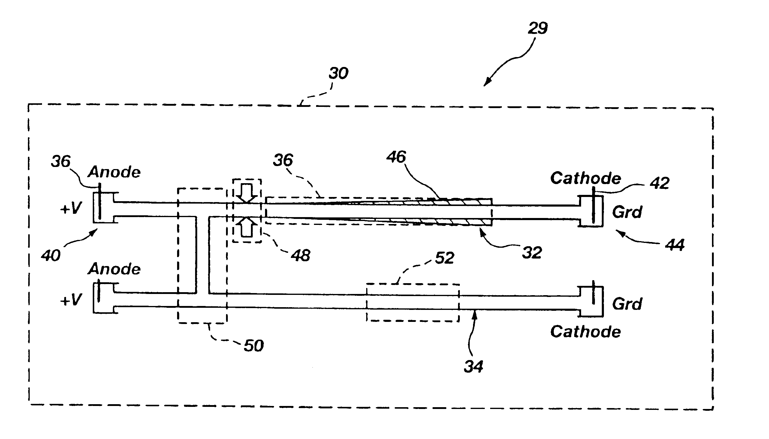
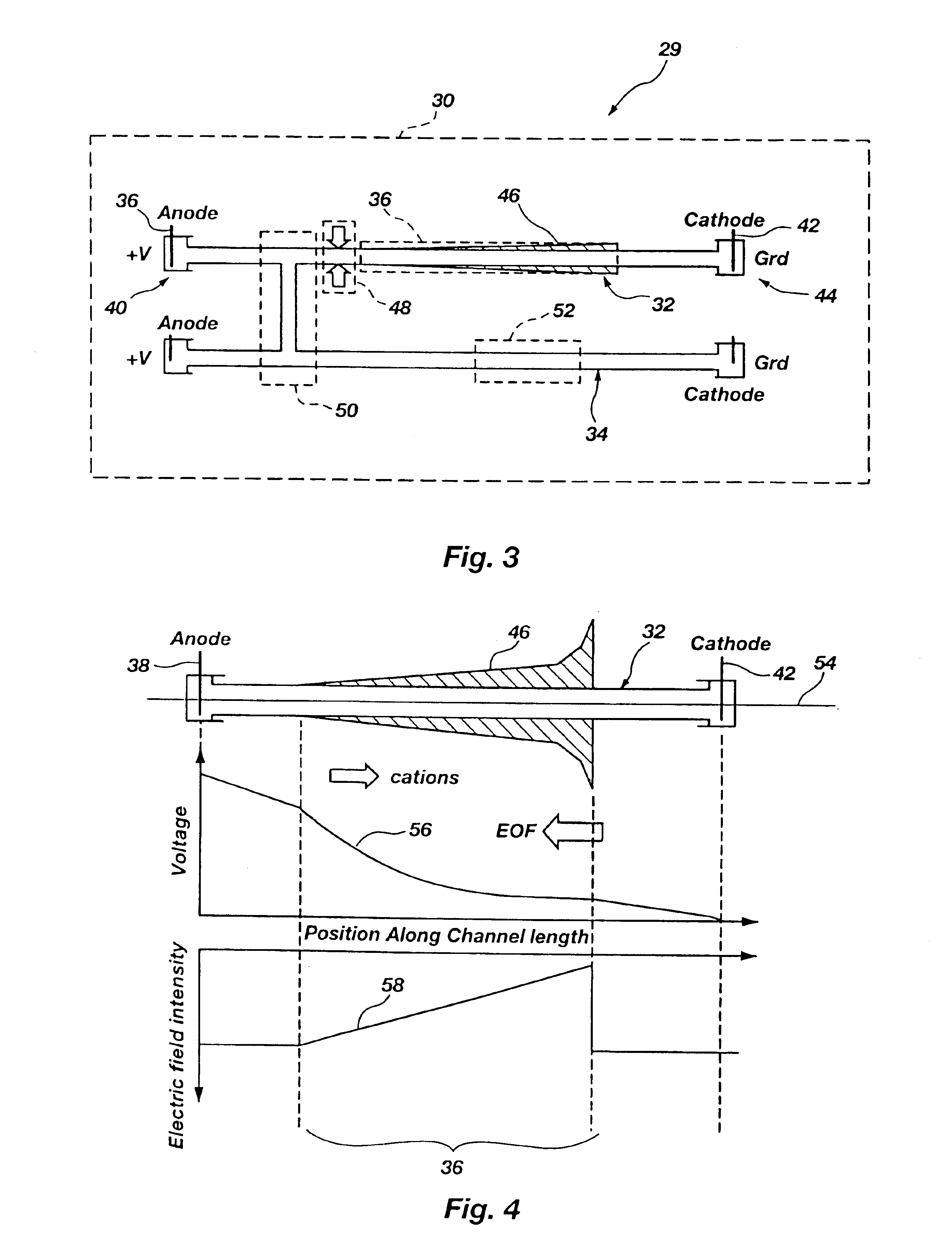
With reference to FIG. 3 of the drawings, which are given by way of example, and not by way of limitation, an electromobility focusing system is embodied in a controlled channel electrophoresis system 29, which comprises in one embodiment a monolith 30 with a first, or primary, separation channel 32 and a second (secondary) channel 34 that are interconnected. It will be appreciated from the discussion below that the system can comprise in one, embodiment only a primary channel, and, moreover, that other variations are possible. A system incorporating several elements and a description of their relationship and function as an example of possible embodiment(s) of the invention will illustrate operative principles. A broad overview will be given, and then individual portions of the system and further details of structure and operation will be described in more detail. The primary channel performs analyte species separation using a continuous electric field intensity gradient (CEFIG) a...


PUM

PropertyMeasurementUnit
DC isolation voltageaaaaaaaaaa
dielectric constantaaaaaaaaaa
diameteraaaaaaaaaa

Abstract

An electromobility focusing controlled channel electrophoresis system includes a first separation channel including an electric field intensity gradient profile in which the intensity is a continuous function of position within the channel over at least a portion of the channel, and the electrophoretic migration facilitated by the electric field is countered by an opposing force, which can be an electroosmotic flow force, to focus analyte species in the separation channel. A second channel including an analyte concentrator and a collection or transfer port is fluidly connected to the first channel by a steering valve facilitating manipulation of separated analyte species. Means for altering and controlling the electroosmotic force for moving analytes within the system and detectors configured for detecting analyte species are also included.

Description

1. Field of the InventionThe invention relates to analytical procedures for investigating analyte species in a fluid sample. More specifically, the invention relates to methods and apparatus for separation and manipulation of analytes, and their application in diagnostic qualitative and quantitative procedures.2. Brief Description of Related ArtElectrormigration separation processes, such as capillary zone electrophoresis and micellular electrokinetic capillary chromatography and other similar processes, are known and are widely used. For example, these processes are used in research and in various testing applications such as separations of proteins and DNA fragments. Control, and particularly fine control, of these processes is an-area of ongoing research and development efforts, as manipulation of quantities of analyte species for separation and qualitative and quantitative analysis is recognized as a significant technical challenge, but one potentially yielding great benefits in...

Claims


Application Information

Patent Timeline
Patent Type & Authority Patents(United States)
IPC IPC(8): G01N27/447
CPCG01N27/44717G01N27/44752G01N27/44773
Inventor LE FEBRE, DAVID
Owner LE FEBRE DAVID
Why Eureka
Try Eureka